 Kia Sorento: ESC Control Module Removal
Second Generation XM (2011-2025) / Kia Sorento XM 2011-2025 Service Manual / Brake System / ESC(Electronic Stability Control) System / ESC Control Module Removal
| 1. |
Turn the ignition switch OFF.
|
| 2. |
Remove the surge tank. [G3.3 GDI]
(Refer to Engine Mechanical System - "Surge Tank")
|
| 3. |
Remove the brake fluid from the master cylinder reservoir with
a syringe.
|
| 4. |
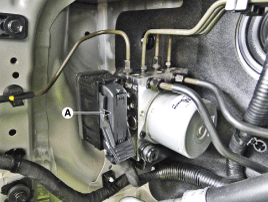
Pull up the lock of the HECU connector (A) and then disconnect
the connector.
|
| 5. |
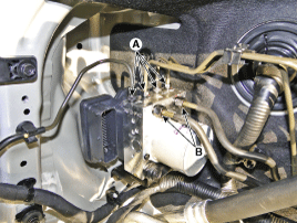
Disconnect the brake tubes from the HECU by unlocking the nuts
counterclockwise with a spanner.
|
| 6. |
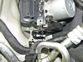
Loosen the HECU bracket nuts (A) and then remove HECU and bracket.
|
| 7. |
Remove the bolts and then remove the bracket from HECU.
|
 ESC Control Module Components
1. Front - left tube
2. Rear - right tube
3. Rear - left tube
4. Front - right tube
5. MC2
6. MC1
7. ESC control module (HECU)
8. Bracket
...
 ESC Control Module Installation
1.
Installation is the reverse of removal.
2.
Tighten the HECU mounting bolts and nuts to the specified torque.
3.
...
See also:
Troubleshooting
Diagnosis And Testing - Power Tailgate System
The power Tailgate system is a complex system containing many components.
In order to perform conclusive testing, or receive outputs the power T ...
Component Location
1. Rear glass defogger relay
2. Rear glass defogger switch
3. Rear glass defogger
...
Idler Removal and Installation
1.
Remove the drive belt.
(Refer to Timing System - "Drive Belt")
2.
Remove the idler(A).
Tightenin ...
Copyright ® www.ksmanual.com 2014-2025


