 Kia Sorento: Installation
| 1. |
Check that the shift lever is placed in the "N" position
|
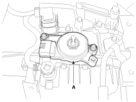
| 2. |
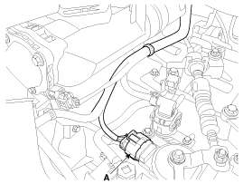
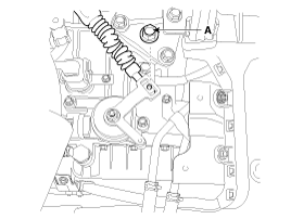
Install the inhibitor switch (A).
|

| 3. |
Install the manual control lever (A).
|
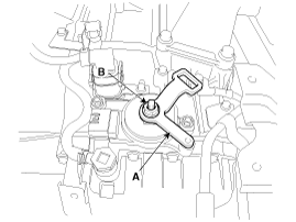
| 4. |
Align the hole (A) in the manual control lever with the "N" position
hole (B) of the inhibitor switch and then insert the SST inhibitor switch
guide pin (09480-A3800).
|
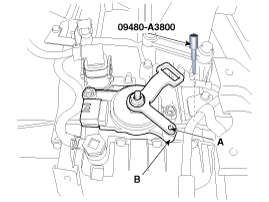
| 5. |
Tighten the nut (A) and bolts (B) with the specified torque.
|
| 6. |
Remove the SST (09480-A3800) from the hole.
|
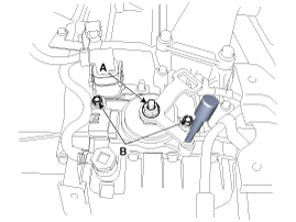
| 7. |
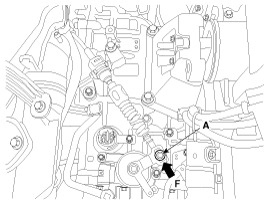
Connect the inhibitor switch connector (A).
|
| 8. |
Install the shift cable by tightening nut (A).
|
| 9. |
Push the shift cable to the arrow "F" to eliminate free play and
then tighten the nut (A) with the specified torque.
|
| 10. |
Install the battery and battery tray.
(Refer to Engine Electrical System - "Battery")
|
| 11. |
Install the air cleaner assembly.
(Refer to Engine Mechanical System - "Air cleaner")
|
 Removal
1.
Place the shift lever into the "N" position.
2.
Remove the air cleaner assembly.
(Refer to Engine Mechanical System - &quo ...
 Shift Lever Components
1. Shift lever mounting bolt
2. Shift lever assembly
3. Shift cable assembly
4. Shift lever knob & boots assembly
5. Manual control lever
6. Retainer
...
See also:
Description
System Operation
Typically, lane departure warning is activated at a speed over 60 km,
but suppressed in case of unintentional lane departure when driver do not operate
turn signal.
S ...
Timing Chain Inspection
Sprockets, Hydraulic Tensioner, Chain Guide, Tensioner Arm, Timing Chain
1.
Check the CVVT sprocket, crankshaft sprocket teeth for abnormal wear,
cracks or damage. Replace ...
Special Service Tools
Tool (Number and Name)
Illustration
Application
RKE Battery Checker
(09954-2P100)
Measuring the RKE battery voltage
Correction ...
Categories
- Home
- First Generation
- Second Generation
- Kia Sorento XM 2011-2026 Owners Manual
- Kia Sorento XM 2011-2026 Service Manual

Copyright ® www.ksmanual.com 2014-2026