
 Kia Sorento: Stop Lamp Switch Repair procedures
Kia Sorento (MQ4, 2021-2026) Service Manual / Brake System / Brake System / Stop Lamp Switch Repair procedures
| Adjustment |
| 1. |
Disconnect the (-) battery terminal.
|
| 2. |
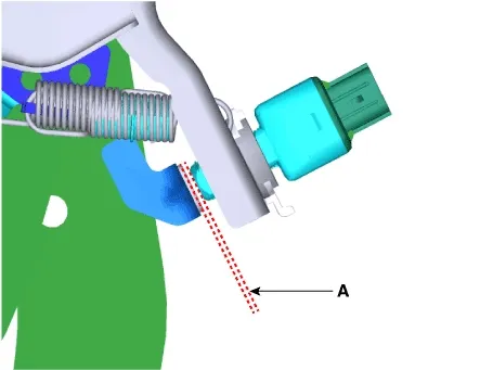
Confirm the gap between stop lamp switch and bracket.
|
| 3. |
If the gap between stop lamp switch and bracket is not 1.0 - 2.0 mm (0.04 - 0.08 in), check the mounting
clip and other part of around stop lamp.
|
| 4. |
If is not normal, remove the stop lamp switch and then install again.
|
| Inspection |
1. Fuse Inspection
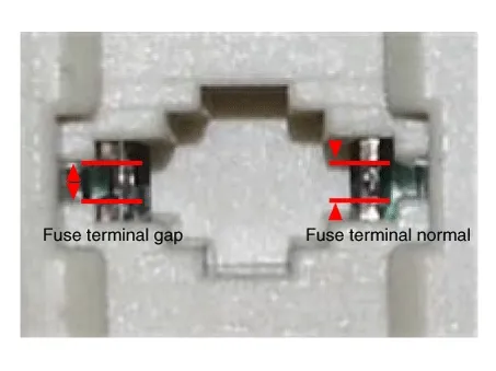
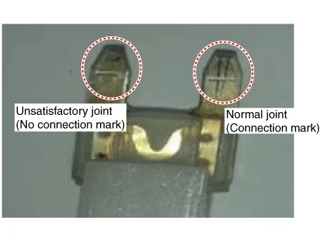
Mount the test fuse to the switch fuse and relay fuse part to confirm a normal joint fit.
2. KDS Data Analysis
| 1. |
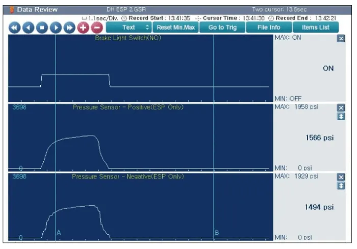
Analyze KDS data and confirm if there is anything wrong with the stop lamp switch.
|
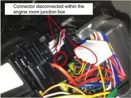
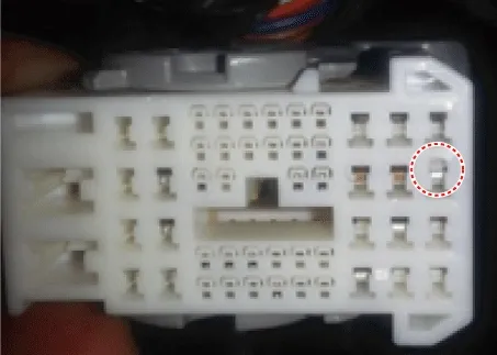
3. Inspection of Connector by Each Part
Check to see whether or not each connector has been damaged, or terminal surge, or incomplete connection has taken
place
[Engine Room Junction Box]
[ABS / ESC Control Module]
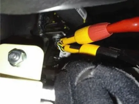
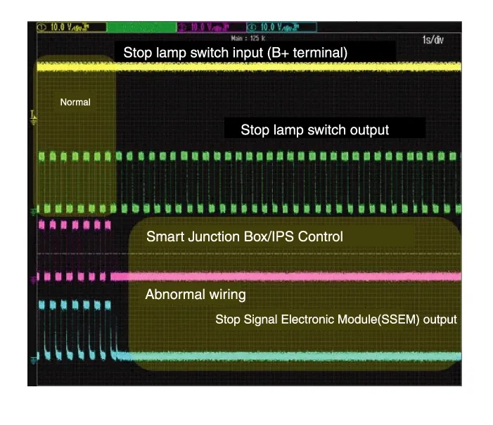
4. Inspect the Stop Lamp Circuit
Connect probe to each terminal wire and confirm oscilloscope waveform.
[Stop Lamp Switch Input / Output]
[Oscilloscope Waveform Screen]
| Removal |
| 1. |
Disconnect the (-) battery terminal.
|
| 2. |
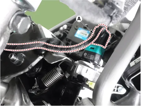
Disconnect the stop lamp switch connector (A).
|
| 3. |
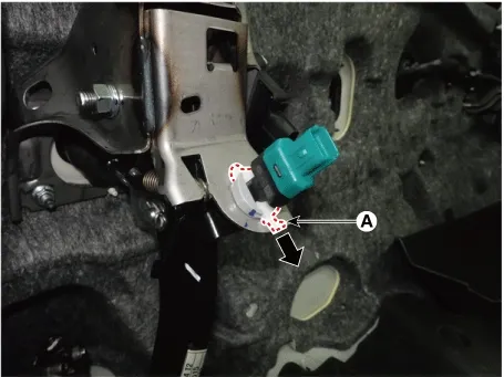
Pull the locking plate (A) as indicated by the arrow.
|
| 4. |
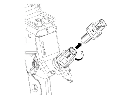
Turn stop lamp switch (A) 45° counterclockwise and remove it.
|
| 5. |
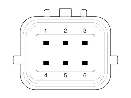
Inspect a removed stop lamp switch along the below procedures.
|
| Installation |
| 1. |
Fix the brake pedal arm and insert fully the stop lamp switch as hiding contact part.
|
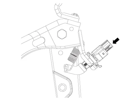
| 2. |
After inserting, turn the stop switch (A) 45° clockwise, and then assemble locking plate by pushing.
|
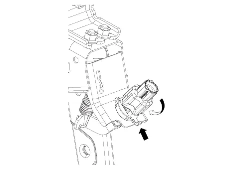
| 3. |
Confirm the gap between stop lamp switch and bracket.
|

| 4. |
Connect the stop lamp switch connector (A).
|
| 5. |
Connect the (-) battery terminal.
|
Troubleshooting
1.
Part diagnosis
Items
Cause
...
 Stop Lamp Switch Troubleshooting
Components
1. Bleed screw2. Guide rod bolt3. Caliper
body4. Guide rod pin5. Guide rod pin seal6. Guide rod pin boot7. Caliper carrier8. Brake
inner...
 Front Brake Caliper Components and Components Location
See also:
Overview. How does the air bag system operate?
Overview
Front Passenger Airbag: Deploys from the upper dashboard assembly to protect the front
occupant
during significant frontal collisions.
...
Troubleshooting
Symptom
Suspect Area
Remedy (Refer to page)
Water leaks from panorama sunroof
Deteriorated roof lid weatherstrip
Replace
Excessive roof lid ...
Description
Limitations Of The Navigation system
GPS Signal Reception State
As the GPS satellite frequency is received/transmitted in straight lines,
reception may not work if hiding devices are pla ...
Manuals list
- Kia Sorento MQ4 2021-2026 Owners Manual
- Kia Sorento XM 2011-2015 Owners Manual
- Kia Sorento XM 2011-2015 Service Manual

Copyright © www.ksmanual.com 2014-2026 - 0.0555