Kia Sorento: Steering Gear Box Repair procedures - Motor Driven Power Steering - Steering SystemKia Sorento: Steering Gear Box Repair procedures

Kia Sorento (MQ4, 2021-2026) Service Manual / Steering System / Motor Driven Power Steering / Steering Gear Box Repair procedures

Removal
1.
Align the steering wheel so that the front wheels to facing straight ahead.
Note
If the steering wheel and the front tires does not synchronize to their centers together, open circuit on the clock spring cable may occur due to change the steering wheel turning.
2.
Disconnect the (-) battery terminal.
3.
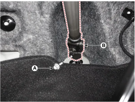
Loosen the bolt (A) and remove the universal joint (B).

Tightening torque :
49.0 - 58.8 N·m (5.0 - 6.0 kgf·m, 36.2 - 43.4 lb·ft)

Steering System — Motor Driven Power Steering / Steering Gear Box / Repair procedures / Removal illustration

Note
•
Secure the steering wheel so that it does not move.
•
Lock the steering wheel in the straight ahead position to prevent the damage of the clock spring inner cable.
•
Do not reuse the bolt.
4.
Remove the front wheel and tire.
(Refer to Tires/Wheels - "Wheel")
5.
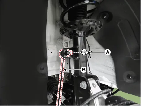
Disconnect the stabilizer bar link (B) with the front strut assembly after loosening the nut (A).

Tightening torque :
98.1 - 117.7 N·m (10.0 - 12.0 kgf·m, 72.3 - 86.8 lb·ft)

Steering System — Motor Driven Power Steering / Steering Gear Box / Repair procedures / Removal illustration

Note
•
When loosening the nut (A), fix the outer hexagon of stabilizer bar link (B).
•
Be careful not to damage the stabilizer bar link boots.
6.
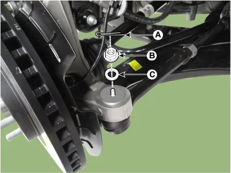
Disconnect the tie rod end ball joint from the knuckle by using the SST (09568-2J100).
(1)
Remove the split pin (A).
(2)
Remove the lock nut (B) and washer (C).

Tightening torque :
98.1 - 117.7 N·m (10.0 - 12.0 kgf·m, 72.3 - 86.8 lb·ft)

Steering System — Motor Driven Power Steering / Steering Gear Box / Repair procedures / Removal illustration

Note
Do not reuse mounting nut.
(3)
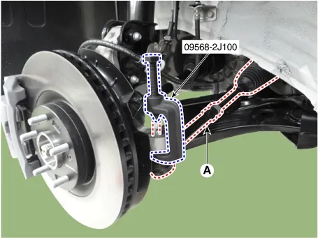
Disconnect the tie rod end ball joint from the knuckle by using the SST (09568-2J100).

Steering System — Motor Driven Power Steering / Steering Gear Box / Repair procedures / Removal illustration

7.
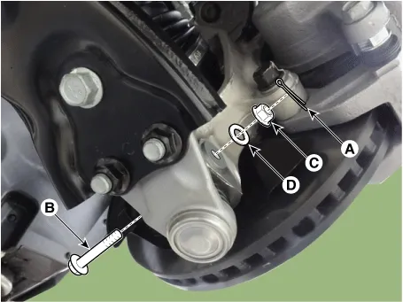
Loosen the lower arm mounting nut (A).
(1)
Remove the split pin (A).
(2)
Remove the lower arm mounting bolt (B), nut (C) and washer (D).

Tightening torque :
98.1 - 117.7 N·m (10.0 - 12.0 kgf·m, 72.3 - 86.8 lb·ft)

Steering System — Motor Driven Power Steering / Steering Gear Box / Repair procedures / Removal illustration

Note
To loosen the nut (C), fix the bolt (B) on the opposite side to prevent it from turning.
8.
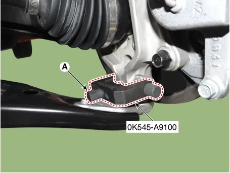
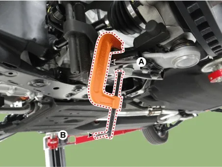
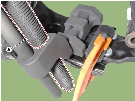
Disconnect lower arm ball joint from the knuckle by using the SST (0K545-A9100).
(1)
After removing bolts from the front knuckle, install and tighten the sub body bolt (A)

Steering System — Motor Driven Power Steering / Steering Gear Box / Repair procedures / Removal illustration

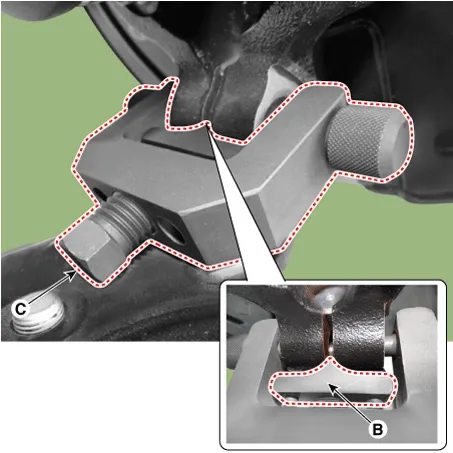
(2)
Input the sub body (B) between the front knuckle and the sub body bolt.
(3)
Tighten the bolt (C) of the sub body to broaden the gap of the front knuckle.

Steering System — Motor Driven Power Steering / Steering Gear Box / Repair procedures / Removal illustration

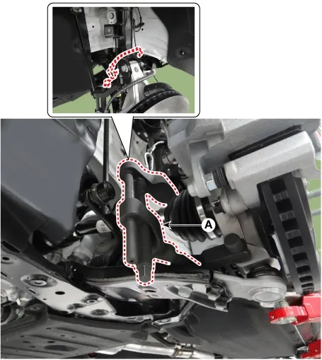
(4)
Install the safe wire and main body (A) between the front strut and the lower arm.

Steering System — Motor Driven Power Steering / Steering Gear Box / Repair procedures / Removal illustration

(5)
After installing a body (A), rotate the handle (B) clockwise util the clamp is fixed on the lower arm.

Steering System — Motor Driven Power Steering / Steering Gear Box / Repair procedures / Removal illustration

(6)
Tighten the main body bolt (A) slowly and remove the lower arm from the front knuckle.

Steering System — Motor Driven Power Steering / Steering Gear Box / Repair procedures / Removal illustration

9.
Remove the under cover.
G 2.5 GDI THETA III - (Refer to Engine Mechanical System - "Engine Room Under Cover")
G 2.5 T-GDI THETA III - (Refer to Engine Mechanical System - "Engine Room Under Cover")
10.
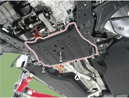
Loosen the nuts and remove the sub frame under cover (A).

Tightening torque :
98.1 - 117.7 N·m (10.0 - 12.0 kgf·m, 72.3 - 86.8 lb·ft)

Steering System — Motor Driven Power Steering / Steering Gear Box / Repair procedures / Removal illustration

11.
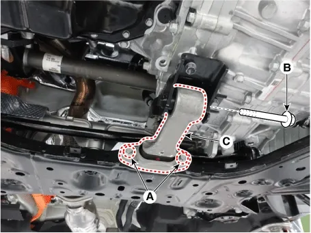
Loosen the mounting bolts (A) and (B) and remove the roll rod bracket (C).

Tightening torque
Bolt (A) : 49.0 - 63.7 N·m (5.0 - 6.5 kgf·m, 36.1 - 47.0 lb·ft)
Bolt (B) : 107.8 - 127.4 N·m (11.0 - 13.0 kgf·m, 79.5 - 94.0 lb·ft)

Steering System — Motor Driven Power Steering / Steering Gear Box / Repair procedures / Removal illustration

12.
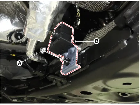
Loosen the nut (A) and remove the muffler rubber hanger (B).

Tightening torque :
19.6 - 24.5 N·m (2.0 - 2.5 kgf·m, 14.4 - 18.0 lb·ft)

Steering System — Motor Driven Power Steering / Steering Gear Box / Repair procedures / Removal illustration

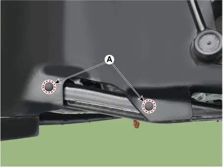
13.
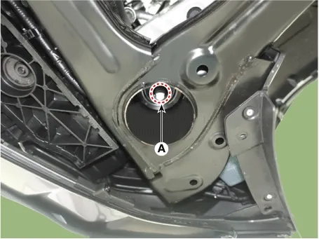
Remove the fastner (A).

Steering System — Motor Driven Power Steering / Steering Gear Box / Repair procedures / Removal illustration

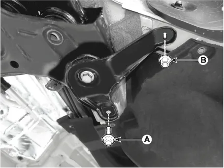
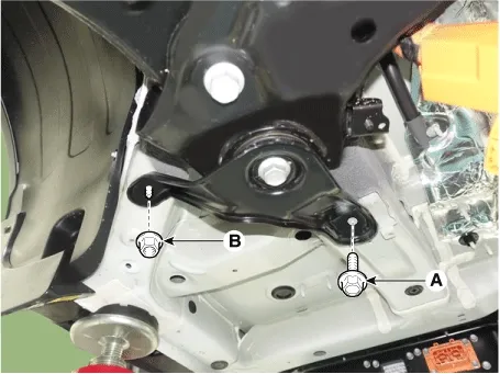
14.
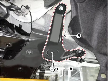
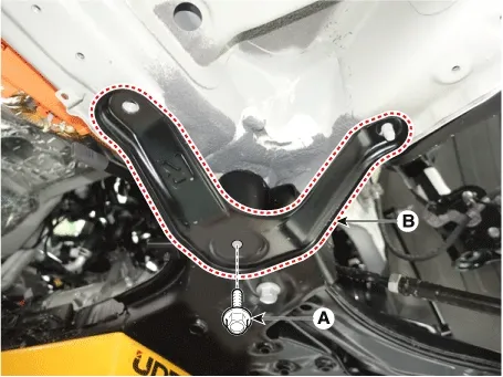
Loosen the sub frame stay bolt (A) and nut (B).

Tightening torque
Bolt (A) : 44.1 - 58.8 N·m (4.5 - 6.0 kgf·m, 32.5 - 43.4 lb·ft)
Nut (B) : 44.1 - 58.8 N·m (4.5 - 6.0 kgf·m, 32.5 - 43.4 lb·ft)

[LH]

Steering System — Motor Driven Power Steering / Steering Gear Box / Repair procedures / Removal illustration

[RH]

Steering System — Motor Driven Power Steering / Steering Gear Box / Repair procedures / Removal illustration

15.
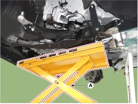
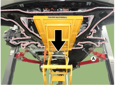
Support the sub frame securely with the jack (A).

Steering System — Motor Driven Power Steering / Steering Gear Box / Repair procedures / Removal illustration

Caution
If the mission jack is used to remove the subframe, it may tip forward, which may cause injury.
16.
Loosen the mounting bolt (A) and remove the front sub frame stay (B).

Tightening torque :
176.6 -196.2 N·m (18.0 - 20.0 kgf·m, 130.1 - 144.6 lb·ft)

[LH]

Steering System — Motor Driven Power Steering / Steering Gear Box / Repair procedures / Removal illustration

[RH]

Steering System — Motor Driven Power Steering / Steering Gear Box / Repair procedures / Removal illustration

17.
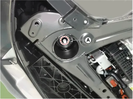
Loosen the sub frame mounting nut (A).

Tightening torque :
176.6 -196.2 N·m (18.0 - 20.0 kgf·m, 130.1 - 144.6 lb·ft)

[LH]

Steering System — Motor Driven Power Steering / Steering Gear Box / Repair procedures / Removal illustration

[RH]

Steering System — Motor Driven Power Steering / Steering Gear Box / Repair procedures / Removal illustration

18.
Slowly lower the jack to remove the sub frame (A).

Steering System — Motor Driven Power Steering / Steering Gear Box / Repair procedures / Removal illustration

19.
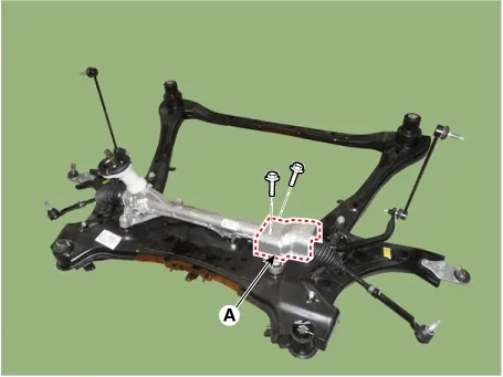
Remove the bolts and remove the steering gear box heat protector (A).

Tightening torque :
6.8 - 10.7 N·m (0.7 - 1.1 kgf·m, 5.0 - 7.9 lb·ft)

Steering System — Motor Driven Power Steering / Steering Gear Box / Repair procedures / Removal illustration

20.
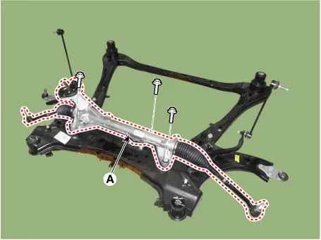
Remove the steering gear box (A) from the front sub frame by removing the mounting bolts.

Tightening torque :
107.9 - 127.5 N·m (11.0 - 13.0 kgf·m, 79.6 - 94.0 lb·ft)

Steering System — Motor Driven Power Steering / Steering Gear Box / Repair procedures / Removal illustration

Replacement
Note
•
Do not disassemble the steering gear box.
•
Except the simple connecting parts, if the noise/cleanliness/functions related parts of the steering gear box replaced, its quality cannot be guaranteed.
[Interchangeable parts]
[C-MDPS]

Steering System — Motor Driven Power Steering / Steering Gear Box / Repair procedures / Replacement illustration

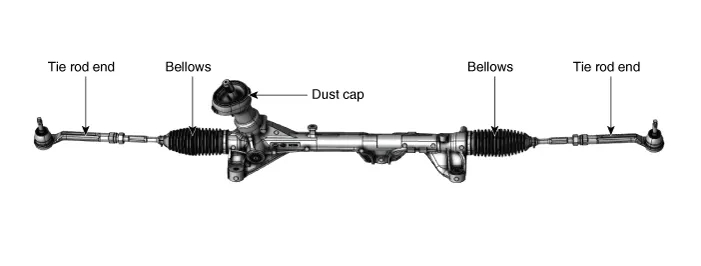
Tie rod end
1.
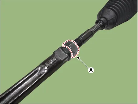
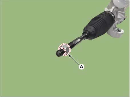
Loosen the tie rod end lock nut (A).

Tightening torque :
49.0 - 53.9 N·m (5.0 - 5.5 kgf·m, 36.2 - 39.8 lb·ft)

Steering System — Motor Driven Power Steering / Steering Gear Box / Repair procedures / Replacement illustration

Note
For easier assembly, measure the length or mark with paint on the thread before loosening the tie rod end lock nut.

Steering System — Motor Driven Power Steering / Steering Gear Box / Repair procedures / Replacement illustration

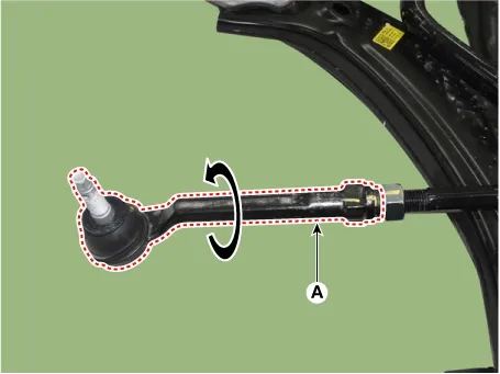
2.
Remove the tie rod end (A) by loosening it in the counter clockwise.

Steering System — Motor Driven Power Steering / Steering Gear Box / Repair procedures / Replacement illustration

3.
Replace the tie rod end with a new one.
4.
Check the alignment.
(Refer to Suspension System - "Alignment")
Bellows
1.
Remove the tie rod end.
(Refer to Replacement - "Tie rod end")
2.
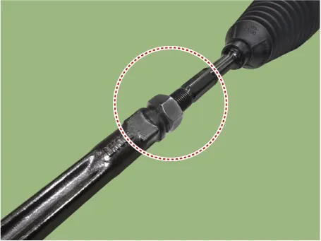
Remove the tie rod end lock nut (A).

Steering System — Motor Driven Power Steering / Steering Gear Box / Repair procedures / Replacement illustration

3.
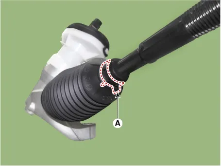
Remove the bellows clamp (A).

Steering System — Motor Driven Power Steering / Steering Gear Box / Repair procedures / Replacement illustration

4.
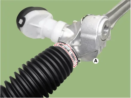
Remove the bellows band (A).

Steering System — Motor Driven Power Steering / Steering Gear Box / Repair procedures / Replacement illustration

Note
•
Be sure to replace the band with a new one.
•
After installing together with the band, assemble the bellows.
5.
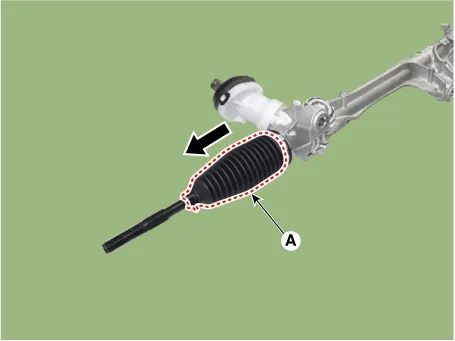
Remove the bellows (A) to the arrow direction.

Steering System — Motor Driven Power Steering / Steering Gear Box / Repair procedures / Replacement illustration

6.
Replace the bellows with a new one.
7.
Check the alignment.
(Refer to Suspension System - "Alignment")
Dust cap
1.
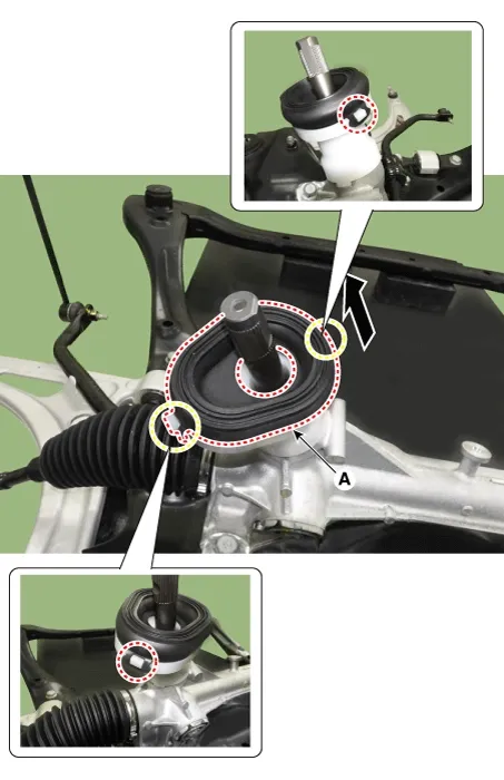
Remove the dust cap cover (A).

Steering System — Motor Driven Power Steering / Steering Gear Box / Repair procedures / Replacement illustration

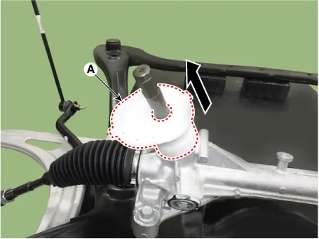
2.
Remove the dust cap (A).

Steering System — Motor Driven Power Steering / Steering Gear Box / Repair procedures / Replacement illustration

3.
Replace the tie rod end with a new one.
Note
•
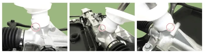
Refer to the drawing below, adjust the parts to the correct position during assembly.

Steering System — Motor Driven Power Steering / Steering Gear Box / Repair procedures / Replacement illustration

•
Assemble the dust cap after cleaning the pinion shaft.
4.
Check the alignment.
(Refer to Suspension System - "Alignment")
Installation
Note
Install the component to the specified torque.
1.
Install in the reverse order of removal.
2.
Perform the "MDPS Tuning Data Setting" by KDS.
(Refer to MDPS System - "Adjustment")
3.
Perform the "SAS Calibration" and "Set the steering feel torque to zero" by KDS.
(Refer to MDPS System - "Adjustment")
4.
Check the alignment.
(Refer to Suspension System - "Alignment")
Steering Gear Box Components and Components Location

Components [C-MDPS] 1. Heat protector2. Dust cap3. Bellows 4. Tie rod end5. Front sub frame...
Tie Rod End Repair procedures
Removal 1. Remove the front wheel and tires. (Refer to Suspension System - "Wheel") 2. ...
See also:

Front Radar On Vehicle Inspection
On Vehicle Inspection Visual inspection If the function of FCA, SCC, NSCC, or HDA 2 is not operable or DTC occurs, check the following below. 1. ...

Power Window Motor Repair Procedures
Removal Front Power Window Motor 1. Remove the front door trim. (Refer to Body - "Front Door Trim") ...

Troubleshooting
Troubleshooting Failure Diagnosis 1. In principle, ESC and TCS controls are prohibited in case of ABS failure. ...

Copyright © www.ksmanual.com 2014-2026 - 0.0516