
 Kia Sorento: Master Cylinder Repair procedures
Kia Sorento (MQ4, 2021-2026) Service Manual / Brake System / Brake System / Master Cylinder Repair procedures
| Removal |
| 1. |
Disconnect the (-) battery cable.
|
| 2. |
Remove the ECM bracket assembly.
G 2.5 GDI THETA III - (Refer to Engine Control / Fuel System - "Engine
Control Module (ECM)")
G 2.5 T-GDI THETA III - (Refer to Engine Control / Fuel System -
"Engine Control Module (ECM)")
|
| 3. |
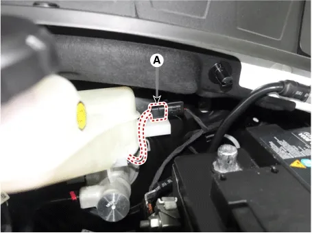
Disconnect the brake fluid level sensor connector (A).
|
| 4. |
Remove the reservoir cap and use the cleaner to drain the brake fluid from the reservoir tank.
|

| 5. |
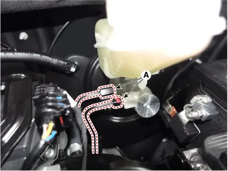
Separate the brake tube (A) from the master cylinder by removing the tube flare nuts.
|

| 6. |
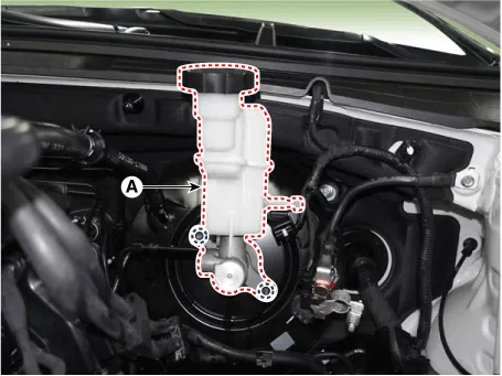
Remove the master cylinder mounting nuts and washer and remove the brake master cylinder (A).
|
| 7. |
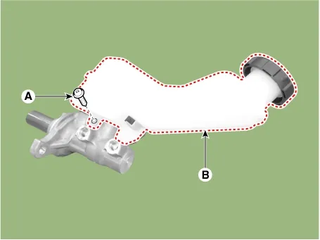
Remove the mounting screw (A) and remove the reservoir tank (B).
|
| 8. |
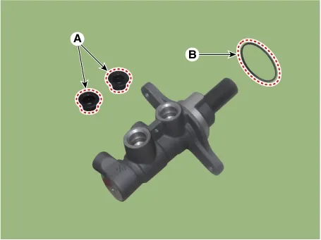
Remove the reservoir grommet (A) and the master cylinder O-ring (B).
|
| Installation |
| 1. |
Install in the reverse order of removal.
|
| 2. |
After installation, bleed the brake system.
(Refer to Brake System - "Brake Bleeding Procedures")
|
| 3. |
Check the brake oil leakage and pedal operating condition.
|
Components
1. Reservoir cap2. Reservoir3. Master
cylinder
4. Brake booster5. Push rod6. Vacuum sensor...
 Master Cylinder Components and Components Location
Vacuum Pump Repair procedures
Removal
[THETA lll 2.5 T-GDI]
1.
Disconnect the battery negative ( - ) ca...
 Vacuum Pump Repair procedures. Brake Line Components and Components Location
See also:
Cooling System Replacement
Replacement and Air Bleeding
[THETA-Ⅲ 2.5 GDI]
...
Rear Differential Carrier Components and Components Location
Components
1. Rear differential carrier assembly2. Differential
carrier bracket
3. Coupling assembly
...
Manuals list
- Kia Sorento MQ4 2021-2026 Owners Manual
- Kia Sorento XM 2011-2015 Owners Manual
- Kia Sorento XM 2011-2015 Service Manual

Copyright © www.ksmanual.com 2014-2026 - 0.0661