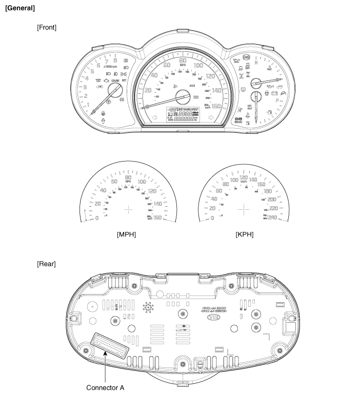
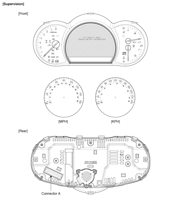
 Kia Sorento: Instrument Cluster Components
Second Generation XM (2011-2026) / Kia Sorento XM 2011-2026 Service Manual / Body Electrical System / Indicators And Gauges / Instrument Cluster Components
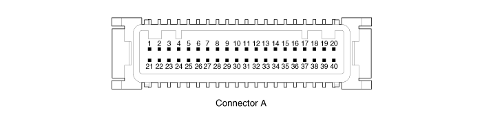
Connector Pin Information
| Pin No. |
Description |
Pin No. |
Description |
| 1 |
Airbag supply |
21 |
Battery |
| 2 |
P (AT) |
22 |
IGN 1 |
| 3 |
R (AT) |
23 |
Illumination (+) |
| 4 |
N (AT) |
24 |
Trip/Reset switch (Trip (+)) |
| 5 |
D (AT) |
25 |
Switch GND (Trip (-)) |
| 6 |
Detent output |
26 |
Signal GND |
| 7 |
Fuel input |
27 |
Fuel low |
| 8 |
- |
28 |
Fuel warning |
| 9 |
Water separator sensor input |
29 |
- |
| 10 |
- |
30 |
- |
| 11 |
Washer input |
31 |
4P output |
| 12 |
Rheostat up |
32 |
- |
| 13 |
Rheostat down |
33 |
C CAN high |
| 14 |
Steering heat |
34 |
C CAN low |
| 15 |
Cruise (+) switch |
35 |
- |
| 16 |
Active ECO |
36 |
M CAN high (Supervision) |
| 17 |
Oil pressure |
37 |
M CAN low (Supervision) |
| 18 |
Alternator |
38 |
- |
| 19 |
Oil level |
39 |
Rheostat output |
| 20 |
Immobilizer |
40 |
Rheostat ground |
 Component Location
1. Cluster assembly
2. Seat belt switch
3. Vehicle speed sensor
4. Engine coolant temperature sender
5. Oil pressure switch
6. Brake fluid level warning switch
7. Parking ...

See also:
Compressor Inspection
1.
Check the plated parts of the disc & hub assembly (A) for color
changes, peeling or other damage. If there is damage, replace the clutch
set.
...
IMS Control Switch Installation
Make sure that the IMS control switch connectors and related connectors
are plugged in properly.
Check the IMS c ...
Categories
- Home
- First Generation
- Second Generation
- Kia Sorento XM 2011-2026 Owners Manual
- Kia Sorento XM 2011-2026 Service Manual

Copyright ® www.ksmanual.com 2014-2026