 Kia Sorento: Installation
| 1. |
Check that the shift lever is placed in the "N" position
|
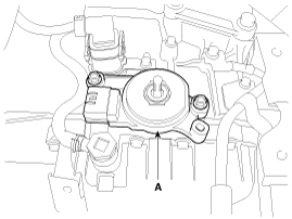
| 2. |
Install the inhibitor switch (A).
|

| 3. |
Install the manual control lever (A).
|
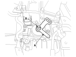
| 4. |
Align the hole (A) in the manual control lever with the "N" position
hole (B) of the inhibitor switch and then insert the SST inhibitor switch
guide pin (09480-A3800).
|
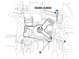
| 5. |
Tighten the nut (A) and bolts (B) with the specified torque.
|
| 6. |
Remove the SST (09480-A3800) from the hole.
|
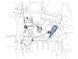
| 7. |
Connect the inhibitor switch connector (A).
|
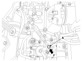
| 8. |
Install the shift cable by tightening nut (A).
|
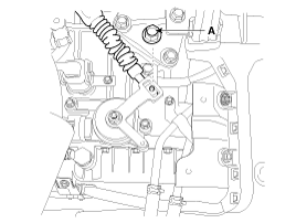
| 9. |
Push the shift cable to the arrow "F" to eliminate free play and
then tighten the nut (A) with the specified torque.
|
| 10. |
Install the battery and battery tray.
(Refer to Engine Electrical System - "Battery")
|
| 11. |
Install the air cleaner assembly.
(Refer to Engine Mechanical System - "Air cleaner")
|
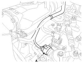
 Removal
1.
Place the shift lever into the "N" position.
2.
Remove the air cleaner assembly.
(Refer to Engine Mechanical System - &quo ...
 Shift Lever Components
1. Shift lever mounting bolt
2. Shift lever assembly
3. Shift cable assembly
4. Shift lever knob & boots assembly
5. Manual control lever
6. Retainer
...
See also:
Maintenance under severe usage conditions
The following items must be serviced more frequently on cars normally used under
severe driving conditions. Refer to the chart below for the appropriate maintenance
intervals.
R : Replace
I : Ins ...
Cruise Control Switch Removal
1.
Disconnect the battery (-) terminal.
2.
Remove the air-bag module from the steering wheel. ( Refer to
RT group)
3.
...
CVVT & Camshaft Components
1. Camshaft bearing cap
2. Camshaft front bearing cap
3. Exhaust camshaft
4. Intake camshaft
5. Exhaust CVVT assembly
6. Intake CVVT assembly
7. Exhaust camshaft upper ...
Categories
- Home
- First Generation
- Second Generation
- Kia Sorento XM 2011-2026 Owners Manual
- Kia Sorento XM 2011-2026 Service Manual

Copyright ® www.ksmanual.com 2014-2026