 Kia Sorento: Inspection
Test the horn by connecting battery voltage to the 1 terminal and ground
the 2 terminal.
The horn should make a sound. If the horn fails to make a sound, replace
it.
Horn Relay Inspection
| 1. |
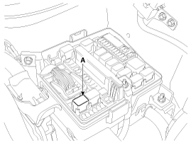
Remove the horn relay (A) from the engine room relay box.
|
| 2. |
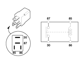
There should be continuity between the No.30 and No.87 terminals
when power and ground are connected to the No.85 and No.86 terminals.
|
| 3. |
There should be no continuity between the No.30 and No.87 terminals
when power is disconnected.
|
 Installation
1.
Install the horns after connecting the horn connectors.
2.
Install the head lamp.
(Refer to "Lighting system")
...
 Adjustment
1.
Operate the horn, and adjust the tone to a suitable level by turning
the adjusting screw.
...
See also:
4WD ECU Components Location
1. 4WD ECU
...
Hill-start assist control (HAC)
A vehicle has the tendency to roll back on a steep hill when it starts to go
after stopping. The Hill-start Assist Control (HAC) prevents the vehicle from rolling
back by applying the brakes automat ...
Rear Differential Carrier Removal
1.
Remove the rear wheel and tire (A) from rear hub.
Tightening torque:
88.2 ~ 107.8 N.m (9.0 ~ 11.0 kgf.m, 65.0 ~ 79.5 lb-ft)
...
Copyright ® www.ksmanual.com 2014-2025


