
 Kia Sorento: Ignition Switch Assembly
Kia Sorento (MQ4, 2021-2026) Service Manual / Body Electrical System / Ignition Switch Assembly
Ignition Switch Repair Procedures
| Removal |
Ignition Switch
| 1. |
Disconnect the negative (-) battery terminal.
|
| 2. |
Remove the steering column upper and lower shroud panel.
(Refer to Body - "Steering Column Shroud Panel")
|
| 3. |
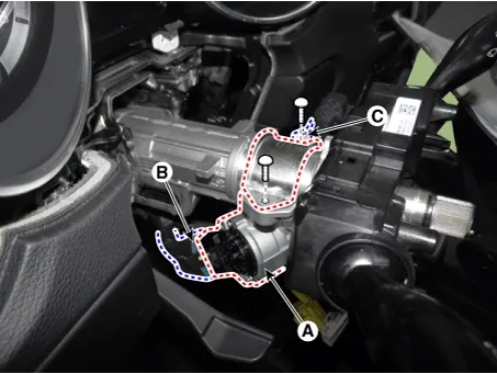
Remove the ignition lock switch assembly (A) by removing the bolts after disconnecting the connectors (B,
C).
|
Key Lock Cylinder
| 1. |
Disconnect the negative (-) battery terminal.
|
| 2. |
Remove the steering column upper and lower shroud panel.
(Refer to Body - "Steering Column Shroud Panel")
|
| 3. |
Insert key and turn it to ACC position.
|
| 4. |
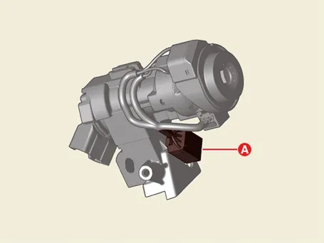
Disconnect the connector (A).
|
| 5. |
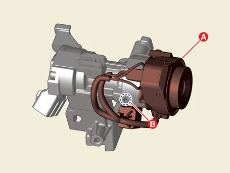
Remove the key lock cylinder (A) after pushing the lock pin (B).
|
| Installation |
| 1. |
Install in the reverse order of removal.
|

| Inspection |
| 1. |
Disconnect the key warning switch connector (A) and ignition switch connector (B) from the steering column.
|
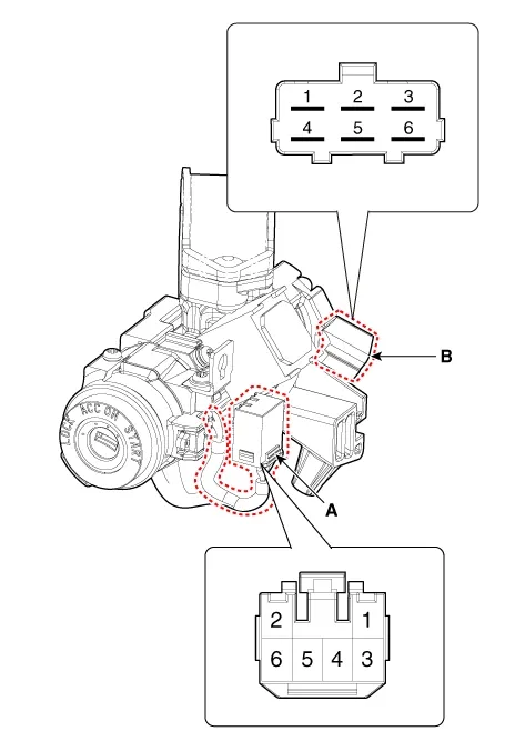
| 2. |
Ignition switch assembly check for continuity between terminals.
|
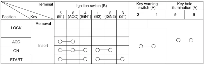
Repair Procedures
Removal
1.
Remove the front bumper assembly.
(Refer to Body - "Front Bumper Assembly")
...
 Horn
 Immobilizer System
See also:
Cooling System Replacement
Replacement and Air Bleeding
[THETA-Ⅲ 2.5 GDI]
...
Power Door Mirror Actuator Inspection
1.
Disconnect the negative (-) battery terminal.
2.
Remove the driver door module.
(Refer to Body - "Front door")
...
Head Lamps Component (1)
1. Head lamp assembly
2. Head lamp high beam bulb
3. Head lamp low beam bulb
4. Dust cap
5. Turn signal lamp socket & bulb
...
Manuals list
- Kia Sorento MQ4 2021-2026 Owners Manual
- Kia Sorento XM 2011-2015 Owners Manual
- Kia Sorento XM 2011-2015 Service Manual

Copyright © www.ksmanual.com 2014-2026 - 0.0575