
 Kia Sorento: High Pressure Fuel Pump Removal and Installation
Kia Sorento (MQ4, 2021-2026) Service Manual / Engine Control / Fuel System / Fuel Delivery System / High Pressure Fuel Pump Removal and Installation
| Removal |
| 1. |
Release the residual pressure in fuel line.
(Refer to the Fuel Delivery System - "Release Residual Pressure in
Fuel Line")
|
| 2. |
Disconnect the battery negative ( - ) terminal.
|
| 3. |
Remove the air cleaner.
(Refer to Engine Mechanical System - "Air Cleaner")
|
| 4. |
Remove the high pressure fuel pipe.
(Refer to Fuel Delivery System - "Fuel Line")
|
| 5. |
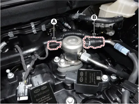
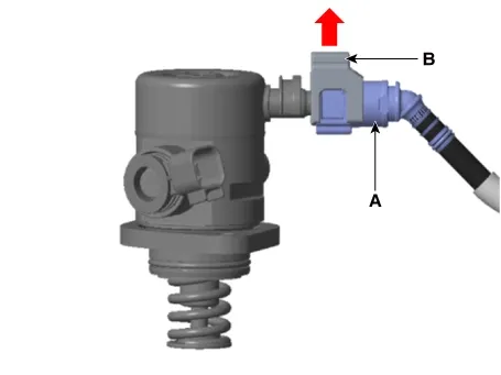
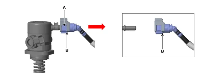
Disconnect the fuel pressure control valve connector (A) and separate the fuel feed tube quick-connector
(B).
|

| 6. |
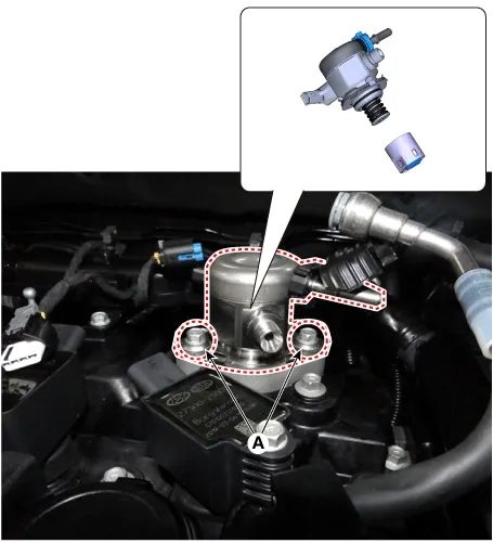
Remove the high pressure fuel pump after removing the mounting bolts (A).
|
| Installation |
| 1. |
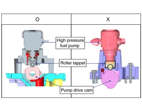
After checking the pump drive cam position, turn the damper pulley to BDC position.
|
| 2. |
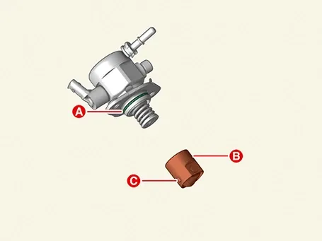
Apply engine oil to the O-ring (A), roller tappet (B), guide pin (C) and mounting groove of the high
pressure fuel pump.
|
| 3. |
After mounting the high pressure fuel pump and the roller tappet, tighten the bolts (A) by hand.
|
| 4. |
Tighten the high pressure fuel pump bolts with specified torque.
|
| 5. |
Connect the fuel pressure control valve connector (A) and the fuel feed quick-connector (B).
|
| 6. |
Install the high pressure fuel pipe.
(Refer to Fuel Delivery System - "Fuel Line")
|
| 7. |
Install the air cleaner.
(Refer to Engine Mechanical System - "Air Cleaner")
|
| 8. |
Connect the battery negative ( - ) terminal.
|
| 9. |
Check for leakage the fuel after installation.
|
Specification
Item
Specification
Coil resistance (Ω)
1.15 - 1.50 [20°C (68°F)]...
 High Pressure Fuel Pump Specifications
Injector Specifications
Specification
Item
Specification
Coil resistance (Ω)
MPI
...
 Injector Specifications. Injector Components and Components Location
See also:
Inspection
1.
Turn the ignition switch OFF.
2.
Disconnect the PCSV connector.
3.
Measure resistance between the PCSV termi ...
E-CVVT Motor Removal and Installation
Special Service Tool
Tool Name / Number
Illustration
Description
A: Electric Continuous Variable Valve Timin ...
Manuals list
- Kia Sorento MQ4 2021-2026 Owners Manual
- Kia Sorento XM 2011-2015 Owners Manual
- Kia Sorento XM 2011-2015 Service Manual

Copyright © www.ksmanual.com 2014-2026 - 0.0535