 Kia Sorento: E-CVVT Motor Removal and Installation
Tool Name / Number
|
Illustration
|
Description
|
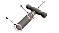
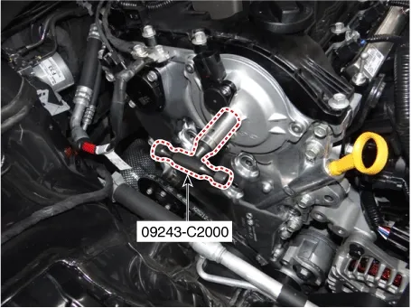
A: Electric Continuous Variable Valve Timing (E-CVVT) plug installer
B: E-CVVT Cover Installer
C :
Handle
09243 - C2000
|
|
Used for installing E-CVVT cover
|
| Electric Continuous Variable Valve Timing (E- CVVT) Cover |
| 1. |
Remove the engine mounting bracket.
(Refer to Engine Mechanical System - "Engine Mounting")
|
| 2. |
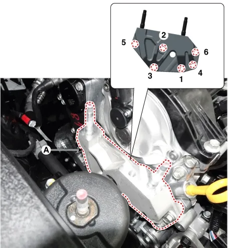
Remove the engine support bracket (A) after loosening the mounting bolts.
Tightening torque :
39.2 - 44.1 N·m (4.0 - 4.5 kgf·m, 28.9 - 32.5 lb·ft)
|
|
loosen in order of 6→5→4→3→2→1
|
|
| 3. |
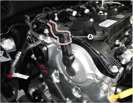
Disconnect the Electric Continuous Variable Valve Timing (E- CVVT) cover connector (A).
|
| 4. |
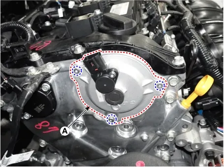
Remove the E-CVVT cover (A) after loosening the bolts.
|
Be careful not to apply the force on the connector brush after removing the E-CVVT cover.
|
|
| Electric Continuous Variable Valve Timing (E- CVVT) Motor |
|
Remove after 30 minutes of switching "OFF" the ignition to drain out the oil inside the Electric
Continuous Variable Valve Timing (E- CVVT) motor plug.
|
| 1. |
Remove the timing chain.
(Refer to Engine Mechanical System - "Timing Chain")
|
| 2. |
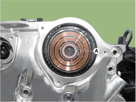
Remove it by breaking the center of E-CVVT motor plug (A).
|
•
|
Do not tilt the front of engine (timing chain cover side) downward as residual oil may flow
out during E-CVVT motor plug removal.
|
|
•
|
If oil flows out during E-CVVT motor plug removal, wipe off immediately and block the motor
shaft inlet with a clean towel.
|
|
|
| 3. |
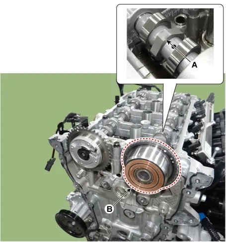
Remove the E-CVVT motor (B) by loosening the mounting bolt after holding the camshaft (A) with a wrench to
prevent the camshaft from rotating.
|
| Electric Continuous Variable Valve Timing (E- CVVT) Motor |
| 1. |
Remove it by breaking the center of Electric Continuous Variable Valve Timing (E- CVVT) motor plug (A).
|
•
|
Remove after 30 minutes of switching "OFF" the ignition to drain out the oil
inside the E-CVVT motor plug.
|
|
•
|
Do not tilt the front of engine (timing chain cover side) downward as residual oil may flow
out during E-CVVT motor plug removal.
|
|
•
|
If oil flows out during E-CVVT motor plug removal, wipe off immediately and block the motor
shaft inlet with a clean towel.
|
|
|
| 2. |
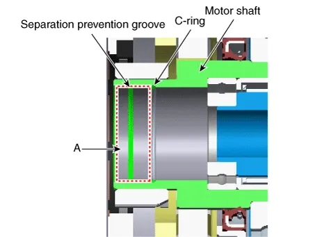
Clean the E-CVVT motor plug mounting surface (A) with oil cleaner.
|
| 3. |
When reusing the E-CVVT cover, inspect the items below.
| (1)
|
If there is sign of leakage from inside the E-CVVT cover, replace it with a new one.
|
| (2)
|
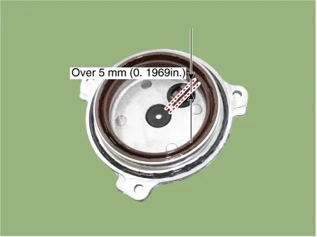
Check for worn connector brush. (If measurement is below specification, replace the E-CVVT cover
with a new one.)
Specification [mm (in.)] : Over 5 (0.1969)
|
|
| (3)
|
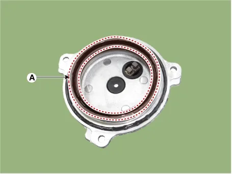
Check for damaged oil seal (A) and replace any damaged E-CVVT cover with a new one.
|
| (4)
|
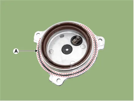
After inspecting E-CVVT, if no problem is found, replace the O-ring (A) with a new one.
|
|
| 4. |
Install the E-CVVT cover.
| (1)
|
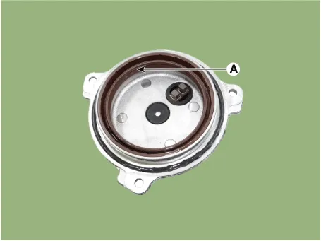
Apply engine oil on oil seal lip (A).
|
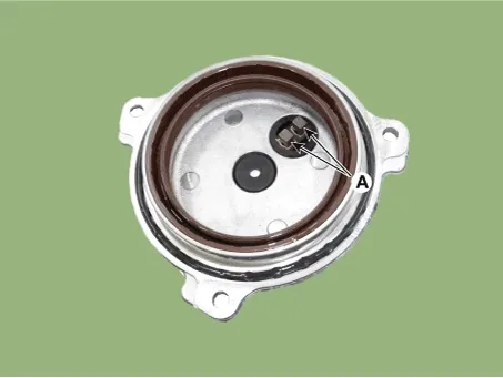
When applying oil, keep the connector brush (A) clean from foreign materials.
|
|
| (2)
|
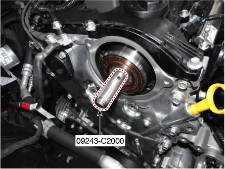
Insert SST (09243 - C2000) into the E-CVVT motor shaft.
|
Insert the SST exactly to motor shaft.
|
|
| (3)
|
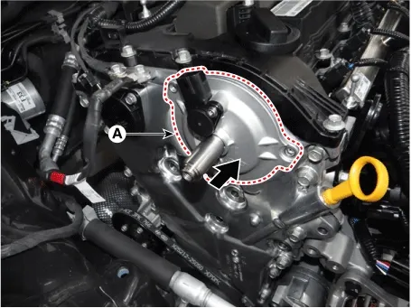
Slowly push the E-CVVT cover (A) until it is flush with the timing chain cover surface.
|
Installing the E-CVVT cover without SST may cause oil leakage inside the E-CVVT motor due
to damaged or separated E-CVVT oil seal.
|
|
| (4)
|
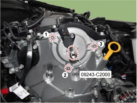
Pre-tighten the bolts in the below sequence, and then remove the SST (09243 - C2000).
Tightening torque :
1.0 - 2.0 N·m (0.1 - 0.2 kgf·m, 0.7 - 1.4 lb·ft, 8.7 - 17.4 lb·in)
|
|
| (5)
|
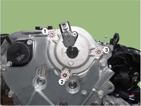
Tighten the bolts to the specified torque in the sequence below.
Tightening torque :
9.8 - 11.8 N·m (1.0 - 1.2 kgf·m, 7.2 - 8.7 lb·ft)
|
|
|
| 5. |
Install the E-CVVT plug.
| (1)
|
By using SST (09243 - C2000), insert the plug (A) into the E-CVVT cover hole.
|
Do not reuse a E-CVVT motor plug.
|
|
| (2)
|
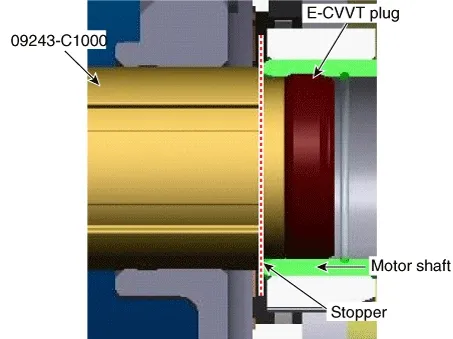
Mount the stopper of SST so that it sits at the end of E-CVVT motor shaft.
|
|
| 6. |
Inspect the pressed depth of E-CVVT plug.
| (1)
|
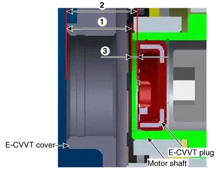
By using a steel ruler, measure the distance from E-CVVT cover center boss to the end of motor
shaft (  ).
|
| (2)
|
By using a steel ruler, measure the distance from E-CVVT cover center boss to the end of E-CVVT
plug (  ).
|
| (3)
|
Measure the pressed depth of E-CVVT plug (  )
(Replace and Reinstall the E-CVVT plug, when it is out of the specification.
Specification [mm (in.)] : 1.1 - 2.1 (0.0433 -
0.0826)
|
|
|
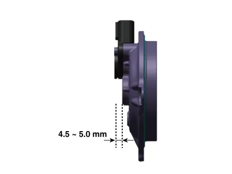
| 7. |
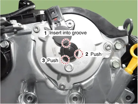
Insert the E-CVVT cover plug so that the guide pin (A) reach to E-CVVT cover groove correctly.
|
•
|
Check how much protrude after installing the E-CVVT plug.
|
|
•
|
Be careful that the plug is not inserted inside E-CVVT cover beyond the regulated range.
|
|
|
| 8. |
Install the engine support bracket (A).
Tightening torque :
39.2 - 44.1 N·m (4.0 - 4.5 kgf·m, 28.9 - 32.5 lb·ft)
|
| (1)
|
Install in order of 1→2→3 temporary.
|
| (2)
|
Turn the bracket counterclockwise and install the bolt 1.
|
| (3)
|
Install in order of 2→3→4→5→6 .
|
|
| 9. |
Install the engine mounting bracket.
(Refer to Engine Mechanical System - "Engine Mounting")
|
| 10. |
Reset the E-CVVT adaptive values by using a KDS.
|
•
|
After replacing or remounting the E-CVVT assembly, be sure to reset the learned value from
the additional feature menu on the KDS diagnostic device.
|
|
•
|
When the learned value for electronic cam position is erased, start learning the cam
position while cranking. The engine can start once this is completed.
|
|
•
|
Cranking should be repeated for up to 2 - 3 times to complete learning.
|
|
|
| Electric Continuous Variable Valve Timing (E- CVVT) Motor |
| 1. |
Install E-CVVT motor (A).
Tightening torque :
73.5 - 83.4 N·m (7.5 - 8.5 kgf·m, 54.2 - 61.5 lb·ft)
|
|
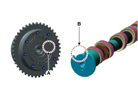
| 2. |
Install the E-CVVT motor (B) by tightening the mounting bolt after holding the camshaft (A) with a wrench
to prevent the camshaft from rotating.
|
Install bolts with tightening torque while E-CVVT stopper (A) and camshaft slot (B) are in contact.
|
|
| 3. |
Install the timing chain.
(Refer to Engine Mechanical System - "Timing Chain")
|
| 4. |
Reset the E-CVVT adaptive values by using a KDS.
|
•
|
After replacing or remounting the E-CVVT assembly, be sure to reset the learned value from
the additional feature menu on the KDS diagnostic device.
|
|
•
|
When the learned value for electronic cam position is erased, start learning the cam
position while cranking. The engine can start once this is completed.
|
|
•
|
Cranking should be repeated for up to 2 - 3 times to complete learning.
|
|
|
E-CVVT Motor Description and Operation
Description
•
Electric Continuous Variable Valve Timing (E-CVVT) system, lo...
On Vehicle Inspection
1.
The engine control system can be more quickly diagnosed for problems with the KDS. (Refer to "DTC
guide")
...
See also:
Specification
Item
Specification
Coil Resistance (Ω)
19.0 ~ 22.0 [20 ...
Bluetooth
The Bluetooth ...
Seat Heater Switch Inspection
Front Seat Heater Switch
1.
Disconnect the negative (-) battery terminal.
2.
Remove the center fascia panel (A).
(Refer to Body - &q ...



 E-CVVT Motor Description and Operation. E-CVVT Motor On Vehicle Inspection
 Engine Control Module (ECM) On Vehicle Inspection
