 Kia Sorento: Heater & A/C Control Unit (DATC) Component
Second Generation XM (2011-2026) / Kia Sorento XM 2011-2026 Service Manual / Heating,Ventilation And Air Conditioning / Controller / Heater & A/C Control Unit (DATC) Component
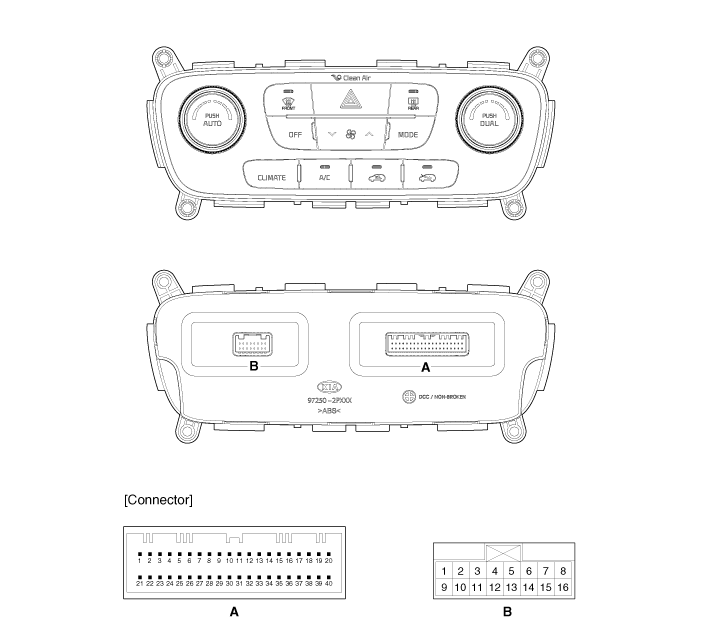
| Connector Pin Function |
| Connector |
Pin No |
Function |
Connector |
Pin No |
Function |
| A |
1 |
Battery (+) |
A |
29 |
Ambient Temperature Sensor (+) |
| 2 |
Tail Lamp (ILL+) |
30 |
Diagnosis (Cluster Ionizer) |
||
| 3 |
IGN2 |
31 |
CLEAN Signal |
||
| 4 |
Mode Control Actuator (Vent) |
32 |
ION Signal |
||
| 5 |
Mode Control Actuator (Defog) |
33 |
PTC ON Signal (Low) |
||
| 6 |
Driver's Side Temperature Control Actuator (Cool) |
34 |
PTC Relay 2 |
||
| 7 |
Driver's Side Control Actuator (Warm) |
35 |
PTC Relay 3 |
||
| 8 |
Intake Actuator (Fresh Air) |
36 |
Rear Blower Relay ON |
||
| 9 |
Intake Actuator (Recirculated Air) |
37 |
ECV IN |
||
| 10 |
Mode Control Actuator Feedback |
38 |
ECV OUT |
||
| 11 |
Driver's Side Temperature Control Actuator Feedback |
39 |
Rear Blower Common Signal (-) |
||
| 12 |
Intake Actuator Feedback |
40 |
Ground |
||
| 13 |
Rheo Detent |
B |
1 |
Sensor REF (+5V) |
|
| 14 |
Hazard Signal |
2 |
- |
||
| 15 |
Ambient Temperature Sensor (+) |
3 |
Passenger's Side Temperature Control Actuator (Cool) |
||
| 16 |
Incar Motor (-) |
4 |
Passenger's Side Control Actuator (Warm) |
||
| 17 |
Blower Motor (+) |
5 |
Passenger's Side Temperature Control Actuator Feedback |
||
| 18 |
Mosfet (DRAIN Feedback) |
6 |
Hi-Scan |
||
| 19 |
Mosfet (GATE) |
7 |
Multi-Media CAN (Low) |
||
| 20 |
Rheostat (ILL-) |
8 |
Multi-Media CAN (High) |
||
| 21 |
IGN1 |
9 |
Defog Temperature |
||
| 22 |
C_CAN (High) |
10 |
Defog SCK |
||
| 23 |
C_CAN (Low) |
11 |
Defog Data |
||
| 24 |
Rear Defog Switch (Low) |
12 |
Auto Defogging Actuator Feedback |
||
| 25 |
HTD (Rear Defog Indicator) |
13 |
Auto Defogging Actuator (OPEN) |
||
| 26 |
Passenger's Side Photo Sensor (-) |
14 |
Auto Defogging Actuator (CLOSE) |
||
| 27 |
Driver's Side Photo Sensor (-) |
15 |
Sensor Ground |
||
| 28 |
Evaporator Temperature Sensor (+) |
16 |
Ground |
 Heater & A/C Control Unit (Manual) Replacement
1.
Disconnect the negative (-) battery terminal.
2.
Using a screwdriver or remover, remove the center fascia panel
(A).
...
 Heater & A/C Control Unit (DATC) Self Diagnosis
1.
Self-diagnosis process
2.
How to read self-diagnostic code
After the display panel blinks three times every 0.5 second, the
...
See also:
Overhead Console Lamp Installation
1.
Install the overhead console lamp after connecting the sunroof
switch connector and lamp connector.
2.
Install the lens after tightening ...
Emergency Fastening Device (EFD) Installation
1.
Remove the ignition key from the vehicle.
2.
Disconnect the negative (-) cable from battery and wait for at
least thirty seconds.
...
Brake Booster Components
1. Brake booster
2. Master cylinder assembly
3. O-ring
...
Categories
- Home
- First Generation
- Second Generation
- Kia Sorento XM 2011-2026 Owners Manual
- Kia Sorento XM 2011-2026 Service Manual

Copyright ® www.ksmanual.com 2014-2026