Kia Sorento: Heater & A/C Control Unit (DATC) Self Diagnosis
1. |
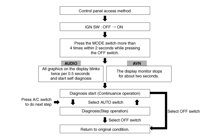
Self-diagnosis process
|
2. |
How to read self-diagnostic code
After the display panel blinks three times every 0.5 second, the
corresponding fault code blinks on the setup temperature display panel
every 0.5 second and will show two figures. Codes are displayed in numerical
format
Fault code
Display
|
Fail Description
|
00
|
Normal
|
11
|
In-car temperature sensor short (Low)
|
12
|
In-car temperature sensor open (High)
|
13
|
Ambient temperature sensor short (Low)
|
14
|
Ambient temperature sensor open (High)
|
17
|
Evaporator sensor short (Low)
|
18
|
Evaporator sensor open (High)
|
19
|
Air mix potentiometer open (Low) - Driver
|
Air mix potentiometer short (High) - Driver
|
21
|
Direction potentiometer open (Low) - Driver
|
Direction potentiometer short (High) - Driver
|
20
|
Air mix motor - Driver
|
22
|
Direction control motor - Driver
|
25
|
Intake potentiometer open (Low)
|
Intake potentiometer short (High)
|
26
|
Intake motor
|
32
|
Air mix potentiometer open (Low) - Passanger
|
Air mix potentiometer short (High) - Passanger
|
33
|
Air mix motor - Passanger
|
44
|
Cluster Ionizer fault
|
31
|
Auto defogging sensor signal and Glass sensor input fault
|
40
|
DEF Direction potentiometer open (Low)
|
DEF Direction potentiometer short (High)
|
41
|
DEF Direction control motor
|
46
|
APT sensor Fault (CAN signal)
|
47
|
Engine RPM Fault (CAN signal)
|
48
|
Vehicle Speed Sensor Fault (CAN Signal)
|
49
|
Engine Coolant Temp Sensor Fault (CAN Signal)
|
|
3. |
Fault code display
(1) |
Continuance operation : None or one DTC code.
|
(2) |
Continuance operation : Two or more DTC code.
|
(3) |
STEP operation
A. |
Nomal or one fault code is same as a continuance
operation.
|
|
|
4. |
If fault codes are displayed while checking, inspect for malfunction
causes by referring to the fault code table.
|
5. |
Fail Safe
No
|
Sensor
|
Fail condition
|
Fail safe function
|
1
|
In-car sensor
|
< 0.1V or > 4.9V
|
23°C (73.4°F)
|
2
|
Ambient temperature sensor
|
< 0.1V or > 4.9V
|
20°C (68°F)
|
3
|
Evaporator temperature sensor
|
< 0.1V or > 4.9V
|
-2°C (28.4°F)
|
4
|
Temperature control actuator feedback
- Driver
|
< 0.1V or > 4.9V
|
• |
Setting temperature is 24.5°C (76.1°F) or below
|
• |
Setting temperature is 25.0°C (77°F) or above:
Max hot
|
|
5
|
Mode control actuator feedback - Driver
|
< 0.1V or > 4.9V
|
|
6
|
Intake actuator feedback
|
< 0.1V or > 4.9V
|
• |
Recirculation: Recirculation
|
|
7
|
Temperature control actuator feedback
- Passenger
|
< 0.1V or > 4.9V
|
• |
Setting temperature is 24.5°C (76.1°F) or below
|
• |
Setting temperature is 25.0°C (77°F) or above:
Max hot
|
|
8
|
Auto defogging sensor (Relative humidity)
|
Communication fail
|
• |
Relative humidity: 60%,
|
• |
Surrounding temperature : 23°C (73.4°F)
|
|
9
|
Auto defogging actuator feedback
|
< 0.1V or > 4.9V
|
|
|
Connector Pin Function
Connector
Pin No
Function
Connector
Pin No
Function
A
1
Battery (+)
A
29
...
1.
Disconnect the negative (-) battery terminal.
2.
Using a screwdriver or remover, remove the center fascia panel
(A).
...
See also:
Blower Resistor Inspection
1.
Measure the resistance between the terminals.
2.
The measured resistance is not within specification, the blower
resistor must be replac ...
Water pump Troubleshooting
Symptoms
Possible Causes
Remedy
Coolant leakage
•
From the bleed hole of the water pump
Visually chec ...
Shift Cable Installation
1.
Install in the reverse order of removal.
Set shift lever and inhibitor ...