
 Kia Sorento: General Service Information
Kia Sorento (MQ4, 2021-2026) Service Manual / General Information / General Service Information
General Information
| General Service Information |
| 1. |
Protect the vehicle's protective painted surfaces and internal parts with work covers (seat covers) or
tape (if damaged by tools) to prevent damage.
|

| 2. |
At the same time as checking the defective part, determine the cause of the failure, determine whether it
is necessary to remove or disassemble, and then work in the order of the workshop manual.
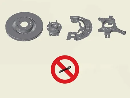
In order to prevent mis-assembly and to facilitate assembly work, punch marks or coincidence marks are
applied to areas that do not adversely affect the function or appearance. When disassembling parts with a
large number of parts and similar parts, arrange them so as not to be confused during assembly.
|
| 3. |
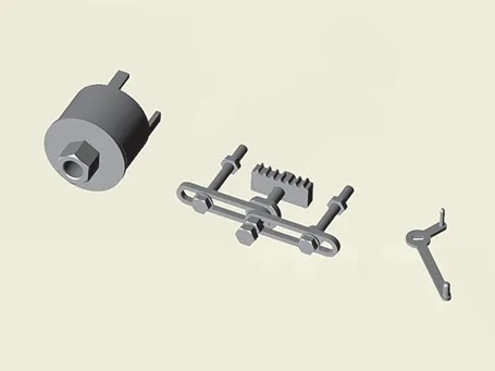
Special tools must be used for work instructing the use of special tools, as the parts may be damaged or
damaged if the work is performed by using tools other than special tools.
|
| 4. |
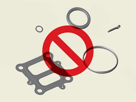
Parts below must be replaced with new ones.
|
| 5. |
Parts
|
| 6. |
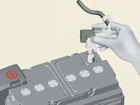
Be sure to turn the ignition switch "OFF" and disconnect the battery negative ( - ) cable before
replacing or repairing electrical system parts.
|
| 7. |
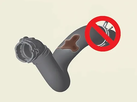
Be careful not to contact fuel and oil with rubber parts and hoses.
|
Inspection of Battery Terminals And Wiring
| 1. |
Check that the battery terminals are solid.
|
| 2. |
Check that the battery terminals and wiring are not corroded by battery electrolyte.
|
| 3. |
Check the battery terminals and wiring for open circuits or the potential to open the circuit.
|
| 4. |
Check the insulation and sheath of the wiring for damage, cracks, and deterioration of quality.
|
| 5. |
Check if the terminals of the battery are in contact with other metal parts (car body or other parts).
|
| 6. |
Make sure that the ground bolt and the body are in full contact.
|
| 7. |
Check the wiring connection.
|
| 8. |
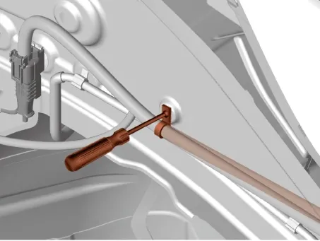
Make sure that the wiring does not come into contact with sharp edges or hot parts (exhaust manifold,
muffler, etc.) on the vehicle body.
|
| 9. |
Make sure that the wiring is secured with sufficient clearance from rotating parts such as cooling fans and
drive belts.
|
| 10. |
Make sure that the wiring has an adequate vibration margin between vibration parts such as engines and
fixed parts such as vehicle bodies.
|
Inspection of Fuse
| 1. |
Check whether the fuse holder firmly secures the fuse.
|
| 2. |
Verify that the fuse capacity is appropriate for each circuit.
|
| 3. |
Inspect the fuse for any signs of damage or malfunction.
|

| 4. |
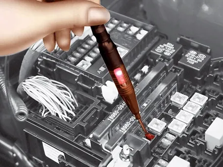
If the fuse is blown or damaged, refer to the electrical circuit diagram and inspect the components
connected to the fuse.
|
| 5. |
If no abnormalities are found in the components, thoroughly check the wiring circuit for any interference
or damage.
|
| 6. |
When replacing a fuse, always use one with the specified rated capacity.
|
Inspection of Electrical System
| 1. |
Be sure to turn the ignition switch "OFF" and disconnect the battery negative ( - ) cable before
replacing or repairing electrical system parts.
|
| 2. |
Fix the wiring with a clamp to prevent stretching.
|
| 3. |
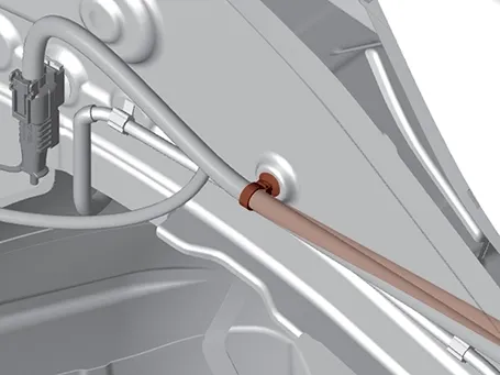
If the wiring contact with the edge or end of the part, wrap the interference part with tape to protect it
from damage.
|
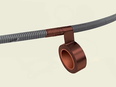
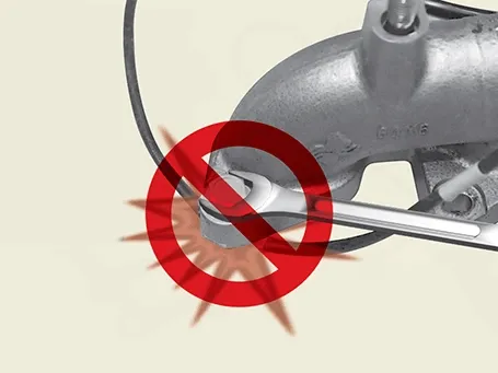
| 4. |
When assembling vehicle parts, be careful not to damage the wiring.
|
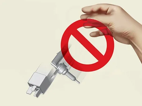
| 5. |
Be careful not to throw or cause shock to relays, sensors, electrical parts.
|
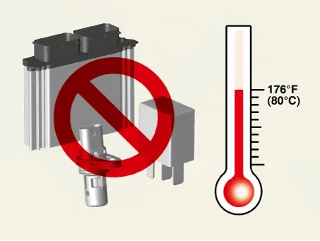
| 6. |
ECMs and relays are easy to get damaged by overheating.
At temperatures above 176°F (80°C), disconnect electrical parts before inspection work.
|
| 7. |
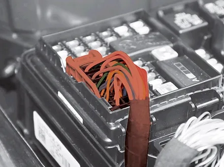
Loose connector connection may cause failure, so make sure that the connector is properly connected.
|
| 8. |
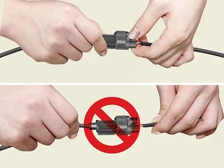
When disconnecting the connector, hold the connector body.
|
| 9. |
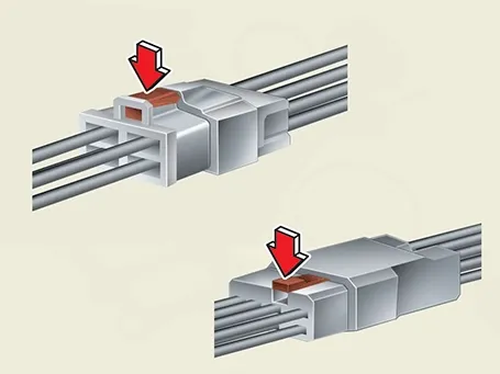
When disconnecting the lockable connector, release the lock as shown below.
|
| 10. |
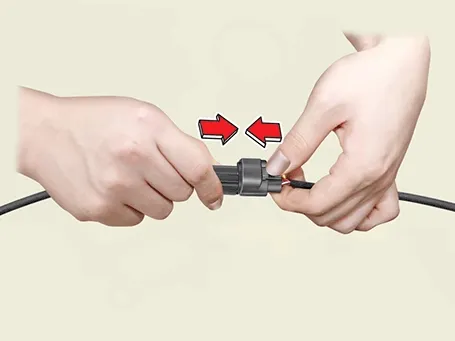
When installing the lockable connector, push it in until a "click" sound is herd.
|
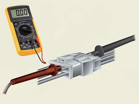
| 11. |
When checking the energization or voltage of a connector terminal with a circuit tester, insert the probe
from the harness side.
If the connector is a sealed type, be careful not to damage the insulation of the wiring, and insert the
probe through the hole in the rubber sheath until the probe touches the terminal.
|
| 12. |
Select appropriate wiring as shown in the table below to prevent overloading the wiring.
|
||||||||||||||||||||||||||||||||||
General Information
Basic Service Symbols
There are five primary symbols used to complement illustrations. These symbols indicate the part to apply such
materials dur...
 Basic Service Symbols
General Information
Identification Numbers
Identification Number Description
Vehicle Identification Number
1.
World Manufacturer I...
 Identification Numbers
See also:
Position Switch Specifications. Position Switch Components and Components Location
Position Switch Specifications
Specification
Item
Specification
Power supply (V)
4.5 - 5.5
...
Gauges. Transmission shift indicator
Gauges
The precision instrument gauges on your Kia Sorento provide real-time operational data, displaying vehicle velocity,
engine performance metrics, fuel status, and thermal conditions to kee ...
Front Camera Adjustment
Special Service Tool
Tool Name / Number
Illustration
Description
Front View Ca ...
Manuals list
- Kia Sorento MQ4 2021-2026 Owners Manual
- Kia Sorento XM 2011-2015 Owners Manual
- Kia Sorento XM 2011-2015 Service Manual

Copyright © www.ksmanual.com 2014-2026 - 0.0673