 Kia Sorento: Front Camera Adjustment
Tool Name / Number
|
Illustration
|
Description
|
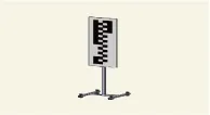
Front View Camera Calibration target
09890 - 3V100
|
|
Used to calibrate the front view camera
|
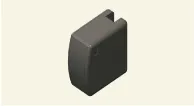
SCC Setting Beam
09964 - C1200
|
|
Used to calibrate the front radar
Used to calibrate the front view camera
|
| Front View Camera Calibration |
|
Perform the front view camera calibration in the following cases.
|
•
|
When the front view camera is reinstalled.
|
|
•
|
When the front view camera is replaced.
|
|
•
|
When the front view camera bracket is deformed.
|
|
•
|
When the windshield glass is replaced.
|
|
•
|
When the DTC occurs for the front view camera.
|
Check the items below before performing the camera calibration.
|
•
|
Align the tires in a straight direction.
|
|
•
|
Inspect the tire pressure.
|
|
•
|
Check the wheel alignment.
|
|
•
|
Check the suspension for damage.
|
|
•
|
Check that the windshield glass is clean.
|
|
| Service Point Target Auto Calibration (SPTAC) |
| 1. |
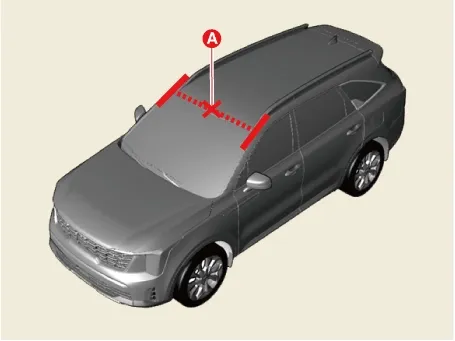
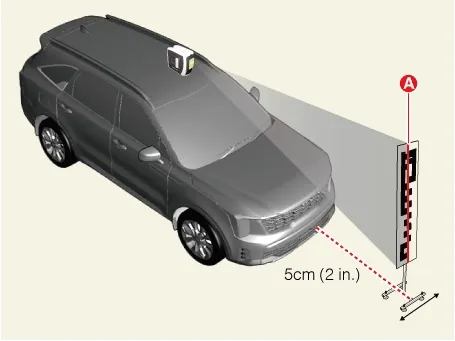
Mark the center point (A) after measuring the distance on top of the windshield glass.
|
| 2. |
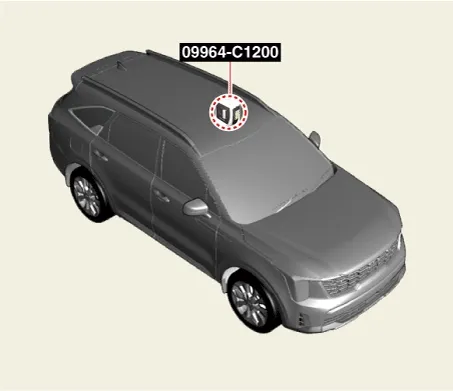
Install the SCC setting beam (09964 - C1200) in the center of the roof.
|
| 3. |
Allow the laser of the SCC setting beam (09964 - C1200) to pass through the center of the emblem.
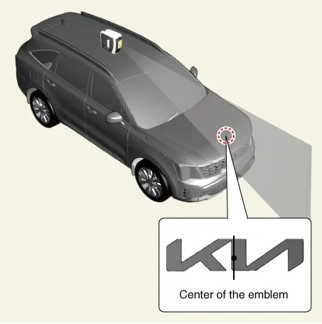
|
The SCC Setting Beam (09964 - C1200) must be set to 'ON' and the holding (locking)
function is not used.
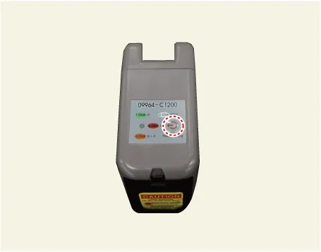
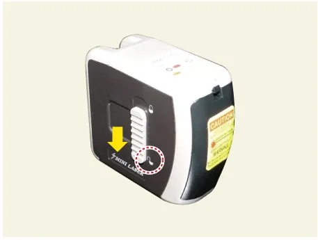
|
|
| 4. |
The height of the front camera calibration target (09890 - 3V100) is adjusted to be 90 ± 2 cm (36 ± 0.8
in.) from the ground.
|
| 5. |
Place the front camera calibration target (09890 - 3V100) so that it maintains a distance of 0 cm (0 in.)
from the bumper. [Maximum tolerance : 10 cm (4 in.)]
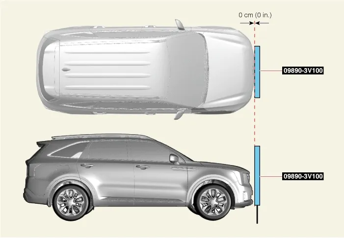
|
| 6. |
Install the front view camera calibration target (09890 - 3V100) center (A) in line with the laser vertical
line of the SCC setting beam (09964 - C1200). [Maximum tolerance : 5cm (2 in.)]
|
•
|
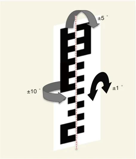
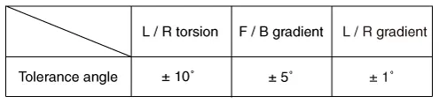
Align the front view camera calibration target (09890 - 3V100) referring to the tolerance
angle below.
|
|
•
|
The vehicle horizontal plane shall be completely parallel to the target horizontal plane (±
1°).
|
|
–
|
The left and right tilt tolerance (±1°) is very important and is sensitively affected by
the flatness of the floor.
|
|
|
| 7. |
Perform the order below with the KDS.
(S/W Management → Front View Camera → SPTAC Calibration)
|
Refer to the KDS screen for operating conditions and details
|
|
| 8. |
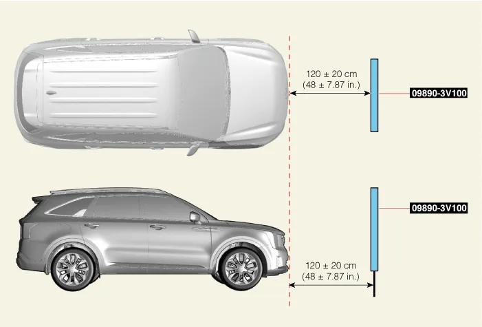
Place the front view camera calibration target (09890 - 3V100) so that it maintains a distance of 120 cm
(48 in.) from the bumper. (Maximum tolerance : 20 cm (8 in.))
|
| 9. |
Install the front view camera calibration target (09890 - 3V100) center (A) in line with the laser vertical
line of the SCC setting beam (09964 - C1200). [Maximum tolerance : 5cm (2 in.)]
|
•
|
Align the front view camera calibration target (09890 - 3V100) referring to the tolerance
angle below.
|
|
•
|
The vehicle horizontal plane shall be completely parallel to the target horizontal plane (±
1°).
|
|
–
|
The left and right tilt tolerance (±1°) is very important and is sensitively affected by
the flatness of the floor.
|
|
|
| 10. |
Perform the order below with the KDS.
(S/W Management → Front View Camera → SPTAC Calibration)
|
Refer to the KDS screen for operating conditions and details
|
|
| 11. |
Check the DTC and warning lamp after erasing the DTC using the KDS.
|
Removal
1.
Perform the order below with the KDS before removing the front camera.
(S/W Management → Front View Camera → System Identificati...
Specification
Item
Specification
Rated voltage (V)
12.0
Operation voltage (V)
9....



 Front Camera Removal and Installation
 Front Corner Radar Specification
