 Kia Sorento: Front Radar Adjustment
Tool Name / Number
|
Illustration
|
Description
|
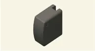
SCC Setting Beam
09964 - C1200
|
|
Used to calibrate the front radar
Used to calibrate the front view camera
|
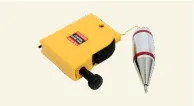
Vertical Plumb
09958 - 3T010
|
|
Used to calibrate the front radar
|
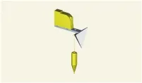
Front Radar Setting Reflector
09964 - C1100
|
|
Used to calibrate the front radar
|
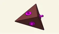
Calibration Reflector
0K964 - J5100
|
|
Used to calibrate the front radar
|
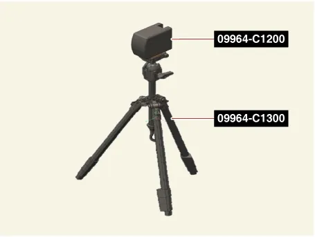
Front Radar Setting Tripod
09964 - C1300
|
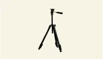
|
Used to calibrate the front radar
|
Front Radar Installation Angle Inspection / Adjustment Overview
|
•
|
The forward radar detects objects in front of the vehicle and measures their speed to recognize the
distance between the vehicle and the objects.
|
|
•
|
If the forward radar angle is not properly calibrated and adjusted, some functions may malfunction.
|
|
The front radar installation angle inspection / adjustment are needed in
the following cases.
|
•
|
When the front radar is reinstalled.
|
|
•
|
When the front radar is replaced.
|
|
•
|
When DTC occurs for the calibration.
|
|
•
|
In the case of damage to the front radar or its periphery.
|
|
•
|
If there is a problem with the front radar detection and recognition function.
|
|
|
•
|
When driving for aobve 10 minutes at 65 km/h after performing the stop mode, correction accuracy is
improved.
(Drive on straight road which has metallic reflector.)
|
|
•
|
When the front radar correction is not available in stop mode, perform the correction in driving
mode.
|
|
Front Radar Mounting Angle Inspection / Correction - Stop Mode
|
Check the following below before performing the front radar mounting angle
inspection / calibration.
|
•
|
Park the vehicle on flat ground.
|
|
•
|
Align the tires in a straight direction.
|
|
•
|
Inspect the tire pressure.
|
|
•
|
Check the wheel alignment.
|
|
•
|
Check the suspension for damage.
|
|
•
|
Check the front bumper or front radar cover bracket is deformed and damaged.
|
|
|
•
|
Perform front radar calibration with the exclusive SST and KDS.
|
|
•
|
Remove objects (metal plates, resins, etc.) that may cause electric signal interference from the
area where front radar alignment is performed.
|
|
•
|
Install the reflector in the correct position. (A calibration of the front radar may fail if the
reflector is not installed in the designated area.)
|
|
•
|
Be sure not to move the vehicle when performing the front radar calibration.
|
|
•
|
Perform the front radar calibration during the IG ON state. (Not EV Ready)
|
|
•
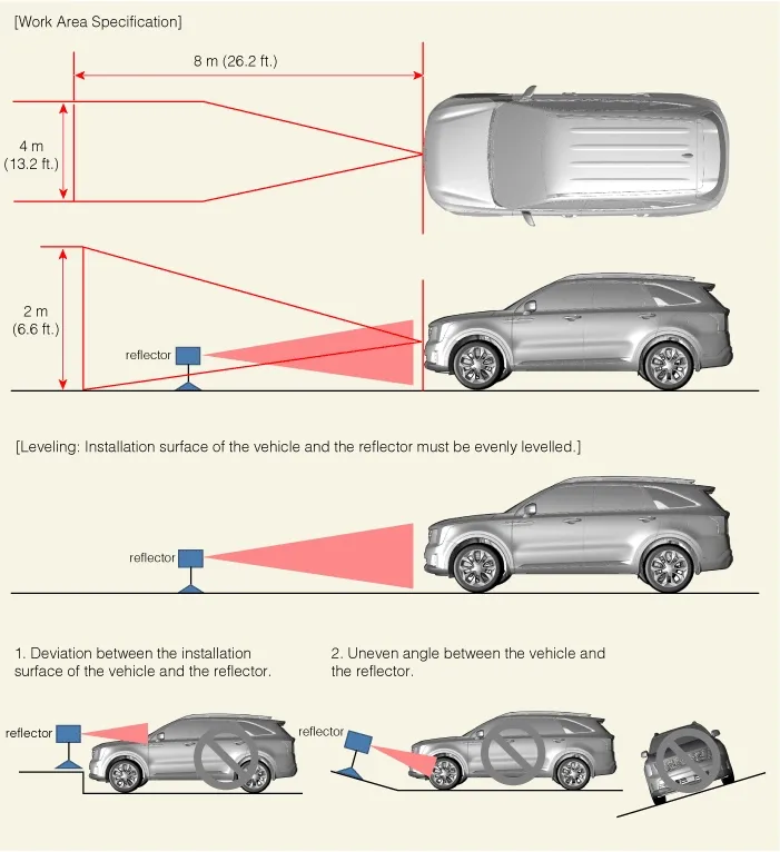
|
Perform the inspection/calibration of the front radar mounting angle in the clearance of 8 m (26.2
ft.) in front of the front bumper, 4 m (13.2 ft.)in width, and 2 m (6.6 ft.) in height.
|
|
| 1. |
Park the vehicle in a flat ground.
|
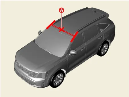
| 2. |
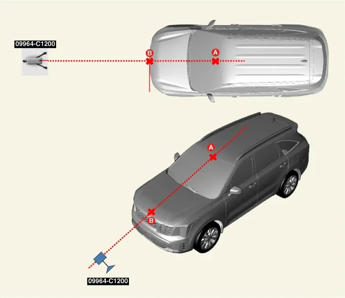
Mark the center point (A) after measuring the distance on top of the windshield glass.
|
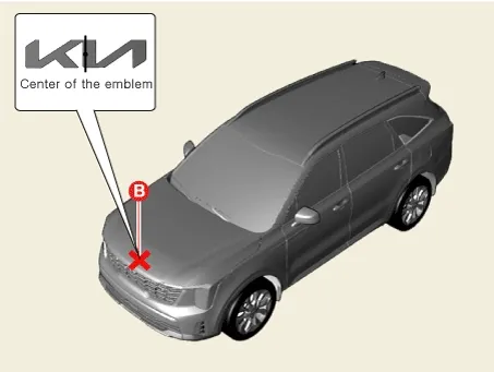
| 3. |
Mark the center point of emblem (B).
|
| 4. |
Mount the SCC setting beam (09964 - C1200) on the front radar setting tripod (09964 - C1300).
|
| 5. |
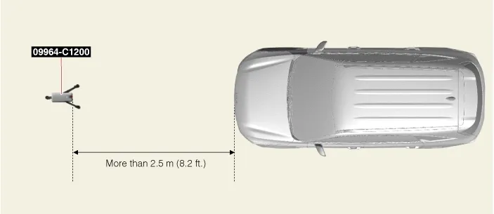
Place the SCC setting beam (09964 - C1200) more than 2.5 m (8.2 ft) away from the front of the vehicle.
|
| 6. |
Match the vertical laser line to points (A) and (B) using the SCC setting beam (09964 - C1200).
|
| 7. |
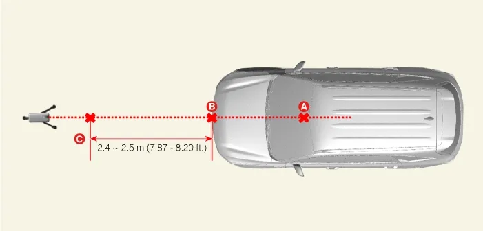
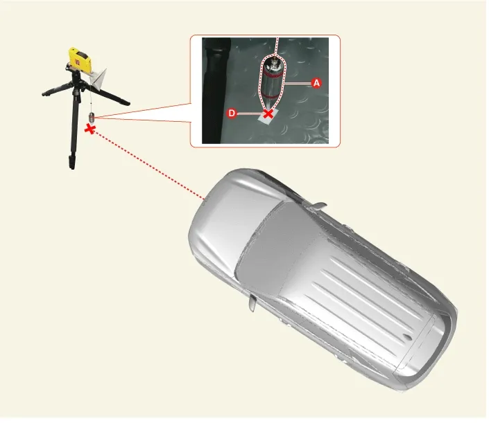
Mark the point (C) at a distance 2.4 - 2.5 m (7.87 - 8.20 ft.) away from (B) point.
|
| 8. |
Mark the location (D) as shown below at 3 mm (0.12 in.) away from (C) to the left (passenger's side)
of the vehicle.
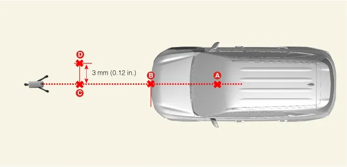
|
| 9. |
Remove the SCC setting beam (09964 - C1200) from the front radar setting tripod (09964 - C1300).
|
| 10. |
Mount the front radar setting reflector (09964 - C1100) to the front radar setting tripod (09964 - C1300).
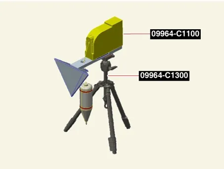
|
| 11. |
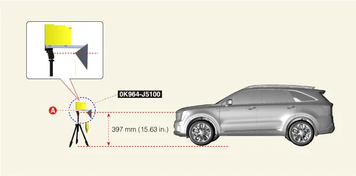
Mount the calibration reflector (0K964 - J5100) to the front radar setting reflector(09964 - C1100).
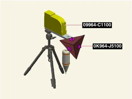
|
| 12. |
Set the reflector horizontal using the leveler (A) which is built in the front radar setting tripod (09964
- C1300).
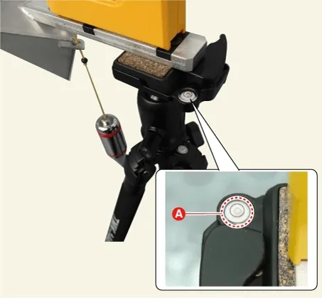
|
| 13. |
Align the plumb (A) of the front radar setting reflector (09964 - C1100) with point (D).
|
| 14. |
Set the height of the calibration reflector (0K964 - J5100) to 397 mm (15.63 in.).
|
| 15. |
Remove the plumb bob from the front radar setting reflector (09964 - C1100).
|
The adjustment of the front radar may be failed if the plumb is not removed.
|
|
| 16. |
Make sure that there is no debris, or reflecting object on the surface of the radar.
|
| 17. |
Perform the order below with the KDS.
(S/W Management → Front Radar → Inspection/correction of the front - radar mounting angle → C1 (Stop mode))
|
Refer to the KDS screen for operating conditions and details
|
|
| 18. |
In case of front radar inspection / correction failure, check the inspection / correction conditions.
|
Front Radar Mounting Angle Inspection / Correction - Driving Mode
|
Check the following below before performing the front radar mounting angle
inspection / calibration.
|
•
|
Inspect the tire pressure.
|
|
•
|
Check the wheel alignment.
|
|
•
|
Check the suspension for damage.
|
|
•
|
Check the front bumper or front radar cover bracket is deformed and damaged.
|
|
|
The driving mode (C2) operates the correction through actual road driving.
(Conducted on roads with metallic fixed reflectors such as guardrails.)
|
| 1. |
Perform the order below with the KDS.
(S/W Management → Front Radar → Inspection/correction of the front - radar mounting angle → C2 (Driving
mode))
|
Refer to the KDS screen for operating conditions and details
|
|
| 2. |
In case of front radar inspection / correction failure, check the inspection / correction conditions.
|
Special Service Tool
Tool Name / Number
Illustration
Description
Digital Inclinometer09958 - 3T1...
On Vehicle Inspection
Visual inspection
If the function of FCA, LKA, BCA, ISLA, DAW, HBA, LFA, HDA or HDA2 is not operable or DTC occurs, check the
following below.
...



 Front Radar Installation
 Front Camera On Vehicle Inspection
