
 Kia Sorento: Engine Mounting Repair procedures
| Removal and Installation |
| 1. |
Remove the engine room under cover.
(Refer to Engine and Transaxle Assembly - "Engine Room Under
Cover")
|
| 2. |
Install the jack to the edge of oil pan to support the engine.
|

| 3. |
Remove the engine mounting support bracket (A).
|
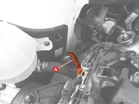
| 4. |
Separate the reservoir tank
(Refer to Cooling system - "Revervoir Tank")
|
| 5. |
Remove the engine mounting bracket (A).
|
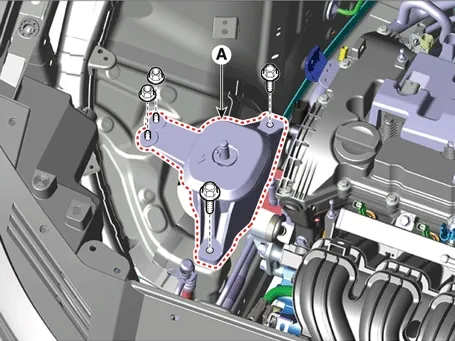
| 6. |
Install in the reverse order of removal.
|
| 1. |
Disconnect the battery negative ( - ) terminal.
|
| 2. |
Remove the air duct and air cleaner assembly.
(Refer to Intake and Exhaust System - "Air Cleaner")
|
| 3. |
Remove the battery and battery tray.
(Refer to Engine Electrical System - "Battery")
|
| 4. |
Remove the LH front wheel guard.
(Refer to Body (Interior and Exterior) - "Front Wheel
Guard")
|
| 5. |
Remove the engine room under cover.
(Refer to Engine and Transaxle Assembly - "Engine Room Under
Cover")
|
| 6. |
Install the jack under the transaxle to support.
|
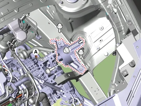
| 7. |
Remove the transaxle support bracket mounting bolts (A).
|
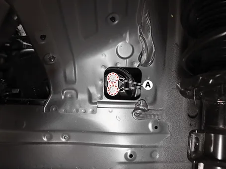
| 8. |
Remove the transaxle support mounting bracket (A).
|
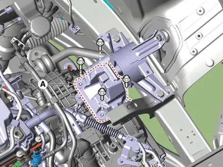
| 9. |
Remove the transaxle mounting bracket (A).
|
| 10. |
Install in the reverse order of removal.
|
| 1. |
Remove the engine room under cover.
(Refer to Engine and Transaxle Assembly - "Engine Room Under
Cover")
|
| 2. |
Remove the roll rod bracket (A).
|
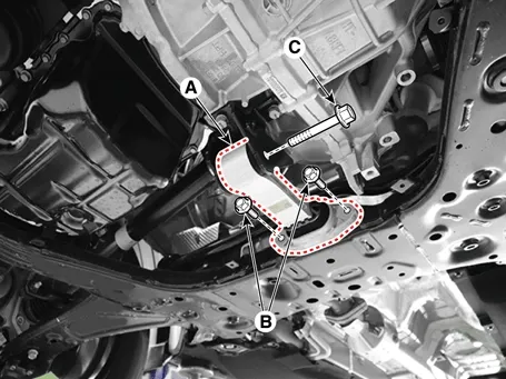
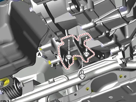
| 3. |
Remove the roll rod mounting support bracket (A).
|
| 4. |
Install in the reverse order of removal.
|
 Engine Room Under Cover Repair procedures. Engine Mounting Components and Components Location
 Engine And Transaxle Assembly Repair procedures
See also:
Automatic release of EPB (if Shift by Wire (SBW) not equipped). EPB warning
Automatic release of EPB (if Shift by Wire (SBW) not equipped)
The Electronic Parking Brake (EPB) in your Kia Sorento is designed to disengage automatically when specific operating
conditions ar ...
Intake Manifold Components and Components Location
Components
1. Intake manifold2. Intake manifold gasket3.
Intake manifold stay4. Electronic Throttle Contorl (ETC)
5. Electronic Thr ...
28 Brake Control Solenoid Valve (28/B_VFS) Installation
Installation
...
Manuals list
- Kia Sorento MQ4 2021-2026 Owners Manual
- Kia Sorento XM 2011-2015 Owners Manual
- Kia Sorento XM 2011-2015 Service Manual
