
 Kia Sorento: Engine And Transaxle Assembly Repair procedures
| Removal and Installation |
|

Mark all wiring and hoses to avoid misconnection.
|

| 1. |
Release the residual pressure in fuel line.
(Refer to Fuel Delivery System - "Release Residual Pressure in Fuel
Line")
|
| 2. |
Disconnect the battery negative ( - ) terminal.
|
| 3. |
Remove the engine cover.
(Refer to Engine and Transaxle Assembly - "Engine Cover")
|
| 4. |
Remove the air duct and air cleaner assembly.
(Refer to Intake and Exhaust System - "Air Cleaner")
|
| 5. |
Remove the battery and bettery tray.
(Refer to Engine Electrical System - "Battery")
|
| 6. |
Remove the engine room under cover.
(Refer to Engine and Transaxle Assembly - "Engine Room Under
Cover")
|
| 7. |
Drain the engine coolant.
(Refer to Cooling System - "Coolant")
|
| 8. |
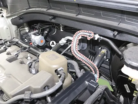
Disconnect the brake booster vacuum hose (A).
|
| 9. |
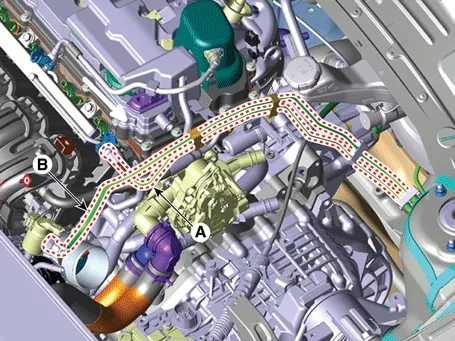
Disconnect the fuel hose (A) and the purge control solenoid valve (PCSV) hose (B).
|
| 10. |
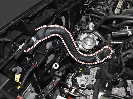
Disconnect the radiator upper hose quick connector (A).
|
| 11. |
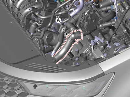
Disconnect the radiator lower hose quick connector (A).
|
| 12. |
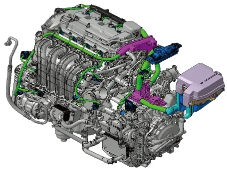
Disconnect the wiring connector and harness clamps and remove the wiring protector around the engine and
transaxle assembly.
|
| 13. |
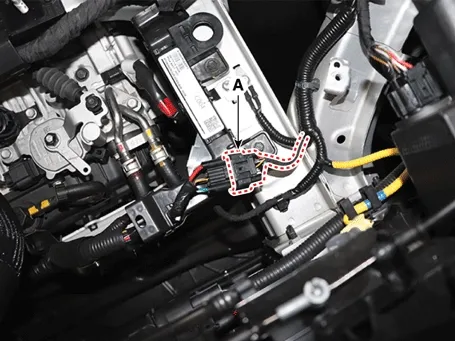
Disconnect the front connector (A).
|
| 14. |
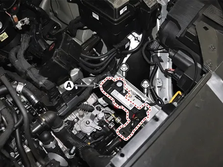
Remove the battery wiring protector (A).
|
| 15. |
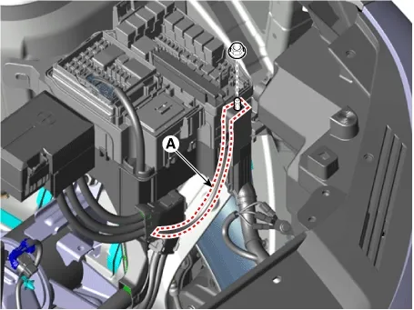
Disconnect the fuse box wiring cable (A)
|
| 16. |
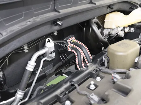
Disconnect the heater hoses (A).
|
| 17. |
Remove the transaxle wire harness connectors and control cable from the transaxle.
(Refer to Automatic Transaxle System - "Automatic
Transaxle")
|
| 18. |
Recover the A/C refrigerant and then remove the A/C compressor high pressure pipe and low pressure pipe.
(Refer to Heating, Ventilation Air Conditioning -
"Compressor")
|
| 19. |
Remove the front muffler.
(Refer to Intake and Exhaust System - "Muffler")
|
| 20. |
Remove the propeller shaft (If equipped with 4WD system)
(Refer to Driveshaft and Axle - "Propeller Shaft Assembly")
|
| 21. |
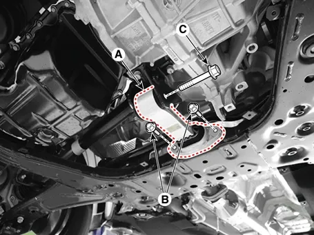
Remove the roll rod bracket (A).
|
| 22. |
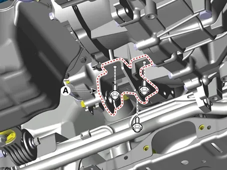
Remove the roll rod mounting support bracket (A).
|
| 23. |
Remove the sub frame.
(Refer to Suspension System - "Sub frame")
|
| 24. |
Support the engine and transaxle assembly with a lift table.
|
| 25. |
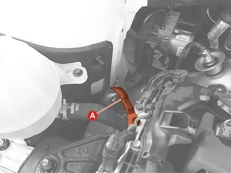
Disconnect the engine ground cable (A).
|
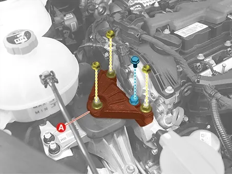
| 26. |
Remove the engine mounting support bracket (A).
|
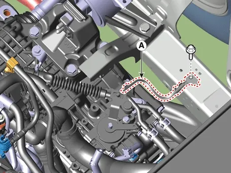
| 27. |
Disconnect the transaxle ground cable (A).
|
| 28. |
Remove the LH front wheel guard.
(Refer to Body (Interior and Exterior) - "Front Wheel
Guard")
|
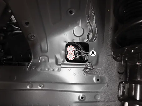
| 29. |
Remove the transaxle support bracket mounting bolts (A).
|
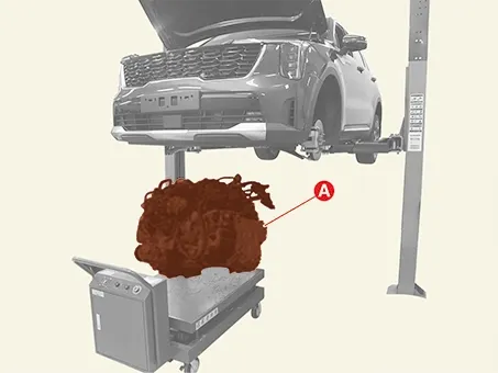
| 30. |
Remove the engine and transaxle assembly by lifting vehicle.
|
| Installation |
| 1. |
Install in the reverse order of removal.
|
| 2. |
Fill the coolant.
(Refer to Cooling System - "Coolant")
|
| • |
Refill a radiator and a reservoir tank with engine coolant.
|
| • |
Inspect for fuel leakage.
|
| – |
After assemble the fuel line, turn on the ignition switch (do not operate the starter) so that the fuel
pump runs for approximately two seconds and fuel line pressurizes.
|
| – |
Repeat this operation two or three times, then check for fuel leakage at any point in the fuel line.
|
| • |
Place a heater control knob on "HOT" position.
|
| • |
Clean the battery terminals and cable terminals with sandpaper, assemble them, and apply grease to prevent
corrosion.
|
 Engine Mounting Repair procedures
 Intake And Exhaust System
See also:
Vehicle Auto Shut-off system
The Vehicle Auto Shut-off system designed for your Kia Sorento powers down the ignition automatically after a
predetermined duration set by the driver, conserving fuel and mitigating the risk of ...
Climate Control Air Filter Replacement
Replacement
1.
Open the glove box (A).
2.
Remove the air d ...
Components
2WD
1. Rear upper arm
2. Rear stabilizer bar
3. Rear lower arm
4. Rear assist arm
5. Rear shock absorber
6. Rear cross member
7. Trailing arm
...
Manuals list
- Kia Sorento MQ4 2021-2026 Owners Manual
- Kia Sorento XM 2011-2015 Owners Manual
- Kia Sorento XM 2011-2015 Service Manual
