
 Kia Sorento: Direct Electro Hydraulic Actuator Coupling Description and Operation
Kia Sorento (MQ4, 2021-2026) Service Manual / All Wheel Drive (AWD) System / Coupling Assembly / Direct Electro Hydraulic Actuator Coupling Description and Operation
| Description |
AWD ECU processes signals from various sensors and determines the current road and driving conditions.
The ECU then utilizes this information to implement precision control over the AWD coupling's multi-plate
clutch and variably adjust the amount of torque delivered tothe rear wheels.
Electric AWD Driving Mode(Terrain Mode)
It makes smooth escape performance by distribution driving power automatically on slippery road such as snowy road
and ice road.
AWD Driving Mode (Terrain Mode)
|
Drive mode |
Information |
| AWD AUTO |
- AWD AUTO is used when driving on roads in normal conditions, roads in urban areas, and on
highways. - All wheels are in operation when a vehicle travels at a constant speed. Required tractions applying on front and rear wheels vary depending on road driving conditions and driv-ing conditions, which will be automatically controlled by the computing system. - When the cluster's AWD display mode is selected, the cluster displays the status of how four wheels’ traction forces are distributed. |
|
SNOW |
- SNOW mode is used to appropriately distribute the vehicle’s traction forces and prevent wheel slippage when
driving on snowy or slippery road. |
|
MUD |
- MUD mode is used to ensure safe driving by appropriately distributing the vehicle’s traction forces when
driving on muddy, unpaved or rough roads. |
|
SAND |
- SAND mode is used to ensure safe driving by appropriately distributing the vehicle’s traction forces when
driving on sandy, graveled or unpaved off-roads. |
Electronic coupling - AWD Control (By Driving Condition)
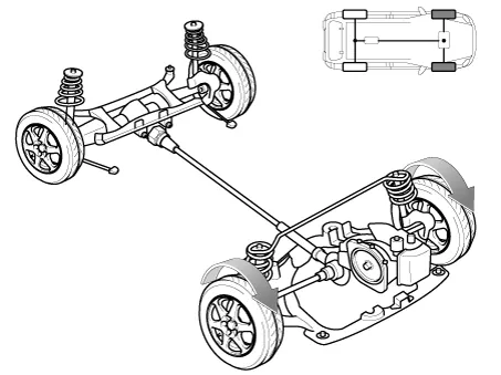
| 1. |
When driving with constant speed
- Power is delivered mostly to the front wheels.
|
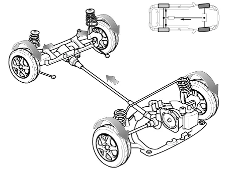
| 2. |
Cornering (Auto Mode)
- Adjusts the amount of power to the rear wheels based on the turning radius and cornering speed
|
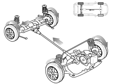
| 3. |
Wheel slip (Auto Mode)
- If one or both of the front wheels lose traction, the system transfers an appropriate amount of power to
the rear wheels based on the slip amount at the front wheels.
|
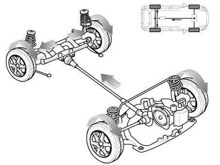
| 4. |
Terrain Mode
- Maximizes rough terrain performance
|
| Operation |
| Electronic coupling |
| [Inactive] |
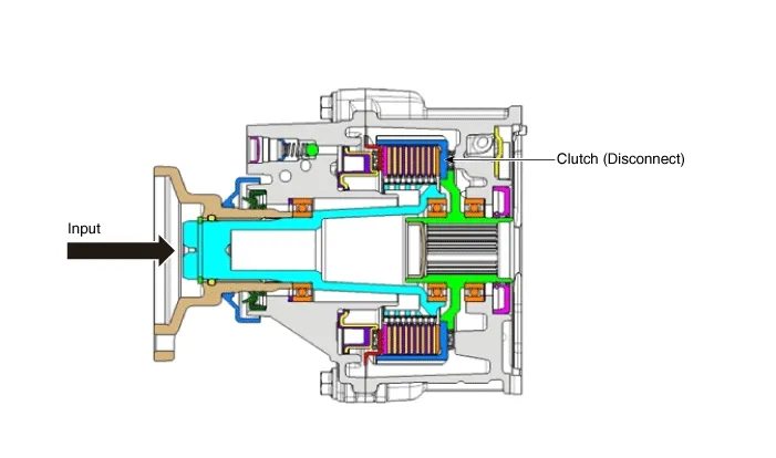
| [Active] |
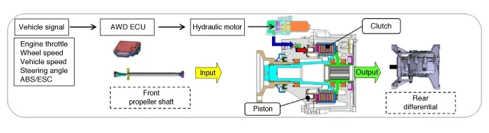
Operation order
| 1. |
AWD ECU receives CAN signals from the vehicle's sensors.
|
| 2. |
AWD ECU calculates the necessary amount of rear-wheel torque and sends the corresponding driving current to
the actuator (electronic motor and hydraulic pump).
|
| 3. |
Hydraulic pressure generated by the actuator moves the piston.
|
| 4. |
Friction from the piston's movement engages the clutch.
|
| 5. |
Power is delivered to the rear wheels.
|
Component Location
Smartstream G 2.5 GDi
1. Automatic transaxle assembly
4. Coupling assembly
2. Transfer as...
 Direct Electro Hydraulic Actuator Coupling Components and Components Location
Inspection
...
 Direct Electro Hydraulic Actuator Coupling Repair procedures
See also:
Battery Sensor Description
Vehicles have many control units that use more electricity. These units
control their own system based on information from diverse sensors. It is important
to have a stable power supply as th ...
Component Location
1. Smart key unit
2. Door handle & door antenna
3. Interior antenna 2
4. Interior antenna 3
5. Tailgate switch
6. Bumper antenna
7. FOB key
8. IPM (Intelligent ...
Oil Temperature Sensor (E-Module) Removal
Removal
...
Manuals list
- Kia Sorento MQ4 2021-2026 Owners Manual
- Kia Sorento XM 2011-2015 Owners Manual
- Kia Sorento XM 2011-2015 Service Manual

Copyright © www.ksmanual.com 2014-2026 - 0.0492