 Kia Sorento: Direct Electro Hydraulic Actuator Coupling Repair procedures
|
All units are filled up with coupling fluid (ultra-low viscosity ATF) prior to shipping. Inspection,
fill-up, and replacement of coupling fluid is therefore not necessary (zero maintenance, lifetime fluid).
|
|
•
|
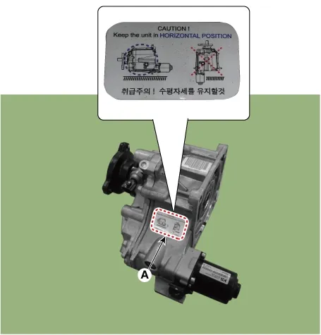
Coupling maintenance precaution.
Refer to the caution label when handling the coupling (removal, installation, replacement, etc.).
|
|
| 1. |
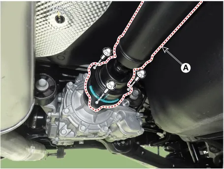
Remove the propeller shaft (A) from the coupling after removing the mounting bolts.
Tightening torque :
53.9 - 68.6 N·m (5.5 - 7.0 kgf·m, 39.8 - 50.6 lb·ft)
|
|
•
|
Do not reuse the bolts.
|
|
•
|
Make a match mark on the propeller shaft flange and coupling flange before removing the
bolts.
|
|
•
|
If abnormal vibration and noise occur at high vehicle speeds after replacing coupling with
a new one, balance the propeller shaft with a balancing machine.
|
|
|
| 2. |
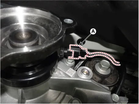
Disconnect the pressure sensor connector (A).
|
| 3. |
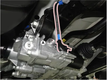
Disconnect the oil hydraulic motor connector (A).
|
| 4. |
Remove the coupling assembly after removing the bolts (A).
Tightening torque :
58.9 - 64.7 N·m (5.8 - 6.6 kgf·m, 41.9 - 47.7 lb·ft)
|
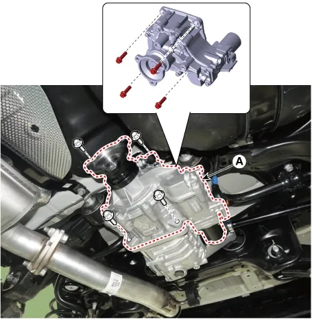
|
| 1. |
Install in the reverse order of removal.
|
•
|
Apply the high pressure grease to the spline (A).
|
|
•
|
Be careful not to damage the oil seal (B) when installing the coupling.
|
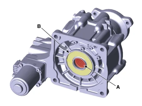
|
|
| 2. |
Perform the clutch learning reset procedure by using the KDS.
(Refer to AWD Control System - "Repair procedures")
|
Description
AWD ECU processes signals from various sensors and determines the current road and driving conditions.
The ECU then utilizes this information to implement precision control...
Description
The AWD ECM controls the Pump Motor Pump (Actuator) to generating an oil pressure. The pressure engages a multiple
disk clutch to transfer torque to the rear wheels. The to...
See also:
Ambient Temperature Sensor Replacement
1.
Disconnect the negative (-) battery terminal.
2.
Remove the front bumper.
(Refer to Body - "Front Bumper")
...
Battery replacement
The transmitter uses a 3 volt lithium battery which will normally last for several
years. When replacement is necessary, use the following procedure.
1. Insert a slim tool into the slot and gently ...
EBD (Electronic Brake-force Distribution)
The EBD system (Electronic Brake force Distribution) as a sub-system of
the ABS system is to control the maximum braking effectiveness by the rear wheels.
It further utilizes the efficiency ...



 Direct Electro Hydraulic Actuator Coupling Description and Operation
 Oil hydraulic Motor(Actuator) Description and Operation
