 Kia Sorento: Cylinder Head Cover Installation
Second Generation XM (2011-2025) / Kia Sorento XM 2011-2025 Service Manual / Engine Mechanical System / Cylinder Head Assembly / Cylinder Head Cover Installation
| 1. |
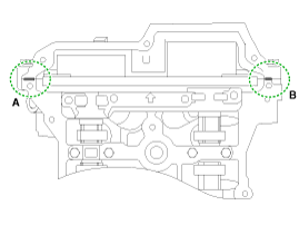
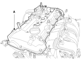
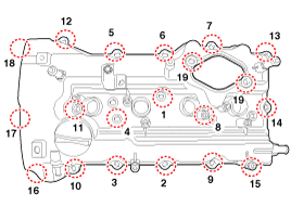
Install cylinder head cover.
|
| 2. |
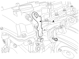
Install the front engine hanger (A).
|
| 3. |
Connect the PCV (Positive crankcase ventilation) hose (A).
|
| 4. |
Install the high pressure fuel pump.
(Refer to Engine Control/Fuel System - "High Pressure Fuel Pump")
|
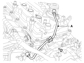
| 5. |
Install the high pressure pipe (A).
|
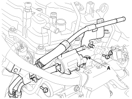
| 6. |
Connect PCSV (Purge control solenoid valve) connector (A) and tighten
the vacuum & PCSV (Purge control solenoid valve) pipe assembly mounting
bolts and nut.
|
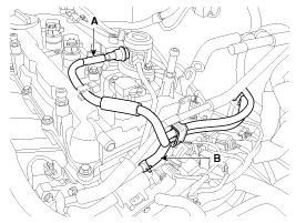
| 7. |
Connect the fuel hose (A) and PCSV (Purge control solenoid valve) hose
(B).
|
| 8. |
Install the ignition coils.
(Refer to Engine Electrical System - "Ignition Coil")
|
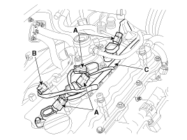
| 9. |
Connect the ignition coil connectors (A) and fuel pump connector (B)
after installing the wiring protector (C).
|
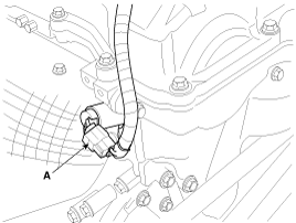
| 10. |
Connect the exhaust OCV (Oil control valve) connector (A).
|
| 11. |
Install the air cleaner assembly.
(Refer to Intake And Exhaust System - "Air Cleaner")
|
| 12. |
Install the engine cover.
|
 Cylinder Head Cover Removal
1.
Disconnect the battery negative terminal.
2.
Remove the engine cover.
3.
Remove the air duct and air cleaner ...
 CVVT & Camshaft Components
1. Camshaft bearing cap
2. Camshaft front bearing cap
3. Exhaust camshaft
4. Intake camshaft
5. Exhaust CVVT assembly
6. Intake CVVT assembly
7. Exhaust camshaft upper ...
See also:
Starter Reassembly
1.
Reassemble in the reverse order of disassembly.
...
CVVT & Camshaft Removal
1.
Remove the cylinder head cover.
(Refer to Cylinder Head Assembly - "Cylinder Head Cover")
2.
Set No.1 cylinder to TDC/comp ...
Component Location
[Engine Room]
1. Receiver-drier
2. Condenser
3. Ambient temperature Sensor
4. Compressor
5. Discharge Hose
6. Suction & Liquid Tube Assembly
7. Servic ...
Copyright ® www.ksmanual.com 2014-2025

