 Kia Sorento: Brake Booster Removal
Second Generation XM (2011-2026) / Kia Sorento XM 2011-2026 Service Manual / Brake System / Brake System / Brake Booster Removal
| 1. |
Turn ignition switch OFF and disconnect the negative (-) battery
cable.
|
| 2. |
Remove the air cleaner assembly.
G 2.4 GDI (Refer to Engine Mechanical System - "Air Cleaner")
G 3.3 GDI (Refer to Engine Mechanical System - "Air Cleaner")
|
| 3. |
Remove the master cylinder.
(Refer to Brake system - "Master cylinder")
|
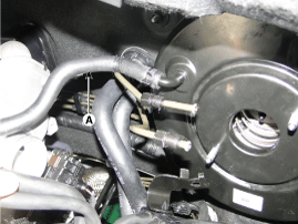
| 4. |
Disconnect the vacuum hose (A) from the brake booster.
|
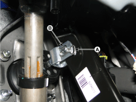
| 5. |
Remove the snap pin (A) and clevis pin (B).
|
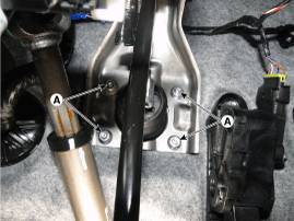
| 6. |
Remove the mounting nuts (A).
|
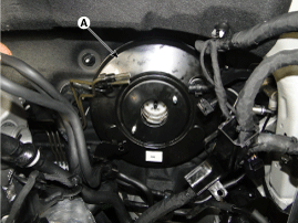
| 7. |
Remove the brake booster (A).
|
 Brake Booster Brake Booster Operating Test
For simple checking of the brake booster operation, carry out the following
tests.
1.
Run the engine for one or two minutes, and then stop it. If the
pedal depresses ...
 Brake Booster Inspection
1.
Inspect the check valve in the vacuum hose, intensifier and the
connecting section.
...
See also:
Occupant Detection system (ODS) Removal
1.
Disconnect the battery negative cable, and wait for at least three
minutes before beginning work.
2.
Remove the front passenger seat ass ...
Speakers Installation
Front speaker
1.
Install the speaker to the speaker mounting hole in the door in-panel.
2.
Reconnect the speaker connector.
Rea ...
For best battery service
Keep the battery securely mounted.
Keep the battery top clean and dry.
Keep the terminals and connections clean, tight, and coated with petroleum
jelly or terminal grease.
Rinse any spill ...
Categories
- Home
- First Generation
- Second Generation
- Kia Sorento XM 2011-2026 Owners Manual
- Kia Sorento XM 2011-2026 Service Manual

Copyright ® www.ksmanual.com 2014-2026