 Kia Sorento: Ladder Frame Removal
Second Generation XM (2011-2025) / Kia Sorento XM 2011-2025 Service Manual / Engine Mechanical System / Cylinder Block / Ladder Frame Removal
|

|

In case of removing the high pressure fuel pump, high pressure fuel
pipe, delivery pipe, and injector, there may be injury caused by leakage
of the high pressure fuel. So donŌĆÖt do any repair work right after engine
stops.
|

| 1. |
Remove the engine assembly from the vehicle.
(Refer to Engine and transaxle assembly - "Engine and Transaxle Assembly")
|
| 2. |
Disconnect the transaxle assembly from engine assembly.
|
| 3. |
Install the engine to an engine stand for disassembly.
|
| 4. |
Remove the intake manifold.
(Refer to Intake And Exhaust System - "Intake Manifold")
|
| 5. |
Remove the exhaust manifold.
(Refer to Intake And Exhaust System - "Exhaust Manifold")
|
| 6. |
Remove the timing chain.
(Refer to Timing System - "Timing Chain")
|
| 7. |
Remove the cylinder head assembly.
(Refer to Cylinder Heae Assembly - "Cylinder Head")
|
| 8. |
Remove the drive plate and the adapter plate.
(Refer to Cylinder Block - "Drive Plate")
|
| 9. |
Remove the balance shaft & oil pump assembly.
(Refer to Lubrication System - "Balance Shaft & Oil Pump")
|
| 10. |
Remove the A/C compressor.
(Refer to Heating, Ventilation, Air Conditioning - "Compressor")
|
| 11. |
Remove the alternator.
(Refer to Engine Electrical System - "Alternator")
|
| 12. |
Remove the water pump assembly.
(Refer to Cooling system - "Water Pump")
|
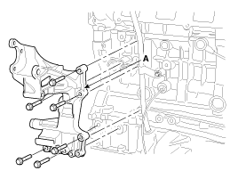
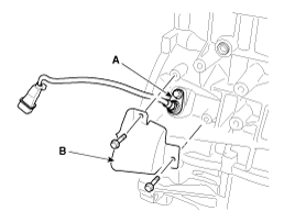
| 13. |
Remove the tensioner assembly integrated bracket (A).
|
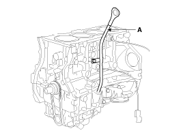
| 14. |
Remove the oil level gauge tube (A).
|
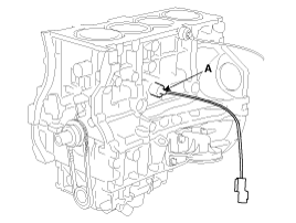
| 15. |
Remove the knock sensor (A).
|
| 16. |
Remove the oil pressure sensor (A).
|
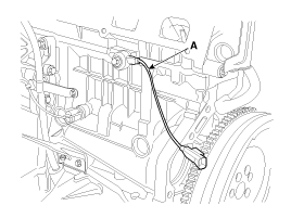
| 17. |
Remove the cover (B) and the CKPS (Crankshaft position sensor) (A).
|
| 18. |
Remove the balance shaft module.
(Refer to Lubrication System - "Balance Shaft & Oil Pump")
|
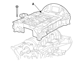
| 19. |
Remove the ladder frame (A).
|
 Rear Oil Seal Installation
1.
Install rear oil seal.
(1)
Apply engine oil to a new oil seal lip.
(2)
Using SST(09 ...
 Ladder Frame Installation
1.
Apply liquid gasket to the mating surface of cylinder block and ladder
frame.
...
See also:
Adjustment
Transaxle Control Module(TCM) Learning
When shift shock is occurred or parts related with the transaxle are replaced,
TCM learning should be performed.
In the following case, TCM learni ...
Antenna Coil Removal
1.
Disconnect the negative (-) battery terminal.
2.
Remove the steering column upper and lower shrouds (A).
3.
...
Driver position memory system (if equipped, for power seat)
A driver position memory system is provided to store and recall the driver seat
and outside rearview mirror position with a simple button operation.
By saving the desired position into the system ...
Categories
- Home
- First Generation
- Second Generation
- Kia Sorento XM 2011-2025 Owners Manual
- Kia Sorento XM 2011-2025 Service Manual

Copyright ® www.ksmanual.com 2014-2025