 Kia Sorento: Cylinder Head Removal
Second Generation XM (2011-2025) / Kia Sorento XM 2011-2025 Service Manual / Engine Mechanical System / Cylinder Head Assembly / Cylinder Head Removal
|

Mark all wiring and hoses to avoid misconnection.
|

In case of removing the high pressure fuel pump, high pressure fuel
pipe, delivery pipe, and injector, there may be injury caused by leakage
of the high pressure fuel. So donŌĆÖt do any repair work right after engine
stops.
|

| 1. |
Remove the intake manifold.
(Refer to Intake And Exhaust System - "Intake Manifold")
|
| 2. |
Remove the exhaust manifold.
(Refer to Intake And Exhaust System - "Exhaust Manifold")
|
| 3. |
Remove the cylinder head cover.
(Refer to Cylinder Head Assembly - "Cylinder Head Cover")
|
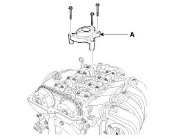
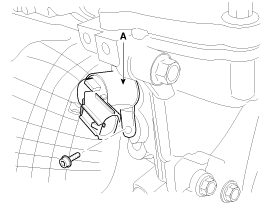
| 4. |
Remove the high pressure fuel pump bracket(A).
|
| 5. |
Remove the timming chain cover.
(Refer to Timing System - "Timing Chain Cover")
|
| 6. |
Remove the timming chain.
(Refer to Timing System - "Timing Chain")
|
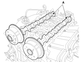
| 7. |
Remove the cmashaft.
|

| 8. |
Remove the intake OCV (Oil control valve) (A) using a torx wrench.
|
| 9. |
Remove the exhaust OCV (Oil control valve) (A) using a torx wrench.
|
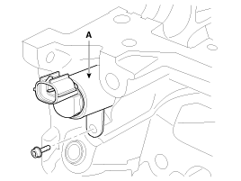
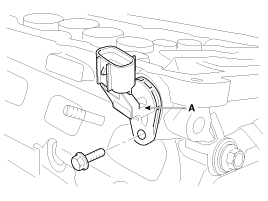
| 10. |
Remove the intake CMPS (Camshaft position sensor) (A).
|
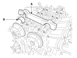
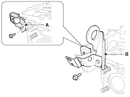
| 11. |
Remove the exhaust CMPS (Camshaft position sensor) (A) after removing
the engine hanger (B).
|
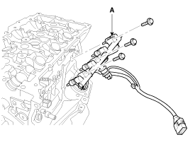
| 12. |
Remove the injector & rail module (A).
|
| 13. |
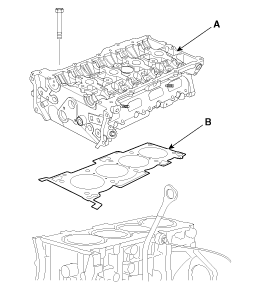
Remove the cylinder head.
|
 Cylinder Head Components
1. Cylinder head
2. Intake OCV (Oil Control Valve)
3. Exhaust OCV (Oil Control Valve)
4. MLA
5. Retainer lock
6. Retainer
7. Valve spring
8. Valve stem seal
9. V ...
 Cylinder Head Disassembly
Identify MLA(Mechanical Lash Adjuster), valves, valve springs as they
are removed so that each item can be reinstalled i ...
See also:
Evaporator Temperature Sensor Description
The evaporator temperature sensor will detect the evaporator core temperature
and interrupt compressor relay power in order to prevent evaporator from freezing
by excessive cooling
...
Specifications
▷ Type: Combination of output signals from 4 terminals
▷ Specifications
Power supply (V)
12
Output type
Pin to Pin
▷ Signal ...
Wave Form
...
Categories
- Home
- First Generation
- Second Generation
- Kia Sorento XM 2011-2025 Owners Manual
- Kia Sorento XM 2011-2025 Service Manual

Copyright ® www.ksmanual.com 2014-2025