 Kia Sorento: Smart key unit Removal
Second Generation XM (2011-2025) / Kia Sorento XM 2011-2025 Service Manual / Body Electrical System / Smart key System / Smart key unit Removal
Smart Key Unit
| 1. |
Disconnect the negative (-) battery terminal.
|
| 2. |
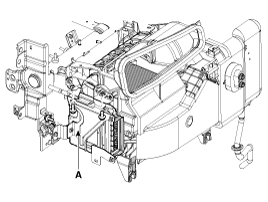
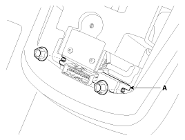
Remove the glove box housing (A).
(Refer to Body - "Crash pad")
|
| 3. |
Remove the smart key unit (A) after removing the bolts and connectors.
|
Interior 1 Antenna
| 1. |
Disconnect the negative (-) battery terminal.
|
| 2. |
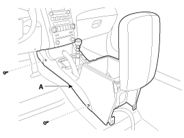
Remove the console assembly (A).
(Refer to Body - "Console")
|
| 3. |
After loosening the antenna bolts (2EA) and connector, remove
the interior 1 antenna (A).
|
Interior 2 Antenna
| 1. |
Disconnect the negative (-) battery terminal.
|
| 2. |
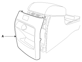
Remove the floor console rear cover (A).
(Refer to Body - "Console")
|
| 3. |
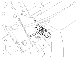
After loosening the antenna nuts (2EA) and connector, remove the
interior 2 antenna (A).
|
Interior 3 Antenna
| 1. |
Disconnect the negative (-) battery terminal.
|
| 2. |
After loosening the mounting bolts, then remove the third seat
assembly (A).
(Refer to Body - "Rear seat")
|
| 3. |
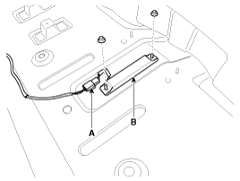
After loosening the antenna nuts (2EA) and connector (A), remove
the interior 3 antenna (B).
|
Exterior Bumper Antenna
| 1. |
Disconnect the negative (-) battery terminal.
|
| 2. |
Remove the rear bumper.
(Refer to Body - "Rear bumper")
|
| 3. |
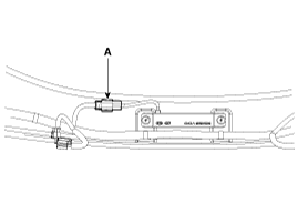
Disconnect the antenna connector (A) on the center of rear bumper.
|
| 4. |
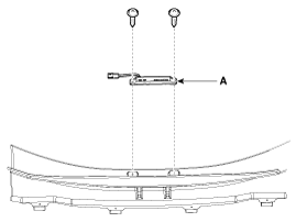
After loosening the screws (2EA), remove the exterior bumper antenna
(A).
|
Buzzer
| 1. |
Disconnect the negative (-) battery terminal.
|
| 2. |
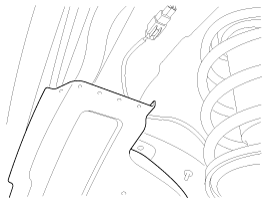
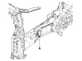
Remove the front left wheel guide.
|
| 3. |
Disconnect the connectors, then remove the buzzer (A).
|
Door Outside Handle
| 1. |
Disconnect the negative (-) battery terminal.
|
| 2. |
Disconnect the connector after removing the door trim.
(Refer to Body - "Front door")
|
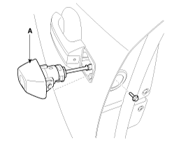
| 3. |
After loosening the mounting bolt, then remove the key holder
(A).
|
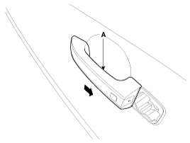
| 4. |
Remove the outside handle (A) by sliding it rearward.
|
Tailgate Switch
| 1. |
Disconnect the negative (-) battery terminal.
|
| 2. |
Remove the tailgate garnish.
(Refer to Body - "Body side molding")
|
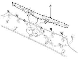
| 3. |
Remove the outside handle panel assembly (A) after removing the
screws and connectors.
|
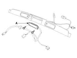
| 4. |
Remove the outside handle (A) after removing the screws.
|
 Smart key unit Inspection
Smart Key Unit
-
Refer to BE group - inspection / self diagnosis with scan tool.
Smart Key Switch
-
Refer to BE group - inspection / self diag ...
See also:
Using Voice Recognition
Starting Voice Recognition
Shortly press the key on the steering
wheel. Say a command
If prompt feedback is in [ON], then the system will say ŌĆ£Please say a command
after the beep (BEEP)ŌĆØ
...
Component Location (1)
1. Smart key unit
2. Interior antenna 3
3. Interior antenna 2
4. Interior antenna 1
5. Buzzer
...
Component Location
1. Start relay #2 (W/O immo./smart key) /
ACC relay (With smart key)
2. Start relay #1
3. Windshield deicer relay
4. Power outlet relay
5. Wiper relay (low)
6. Burgla ...
Copyright ® www.ksmanual.com 2014-2025

