 Kia Sorento: Rear Hub - Carrier Removal
| 1. |
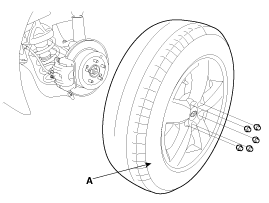
Remove the front wheel and tire (A) from front hub.
|
| 2. |
Remove the rear brake caliper.
(Refer to Brake System - "Rear Disc Brake")
|
| 3. |
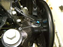
Remove the wheel speed sensor (A), from the knuckle.
|
| 4. |
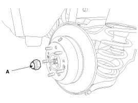
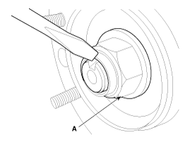
Remove the coking nut (A).
|
| 5. |
Remove the parking brake cable.
(Refer to Brake System - "Parking Brake Cable")
|
| 6. |
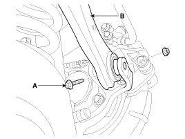
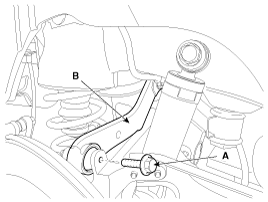
Remove the rear upper arm (A) after loosen the bolt (B).
[2WD]
[4WD]
|
| 7. |
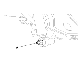
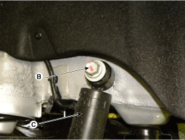
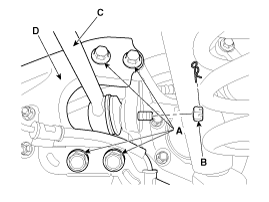
Remove the rear strut assembly (C) after loosen the bolt (B) and
nut (A).
|
| 8. |
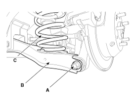
Remove the rear lower arm (B), spring (C) as loosening bolt (A)
after supporting rear lower arm (B) with jack.
|
| 9. |
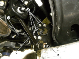
Remove the rear assist arm (C), trailing arm (D) as loosening
bolt (A), nut (B).
[2WD]
[4WD]
|
| 10. |
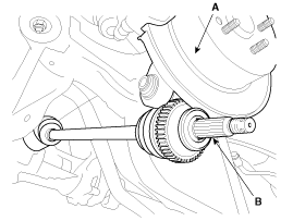
Separate the end (B) of rear driveshaft on rear axle assembly
(A).
|
| 11. |
Install in the reverse order of removal.
|
| 12. |
Check the wheel alignment.
(Refer to Suspension System - "Alignment")
|
 Rear Hub - Carrier Components
1. Rear carrier assembly
2. Parking brake assembly
3. Rear hub assembly
4. Rear brake disc
...
 Rear Hub - Carrier Disassembly
1.
Remove the hub assembly mounting bolts (A-4ea) from the rear axle
carrier (B).
Tightening torque:
78.5 ~ 88.3N.m (8.0 ~ 9.0 ...
See also:
Brake Booster Brake Booster Operating Test
For simple checking of the brake booster operation, carry out the following
tests.
1.
Run the engine for one or two minutes, and then stop it. If the
pedal depresses ...
Output Speed Sensor Description
The output speed sensor (A) is a vital unit that measures the rate of
rotation of the transaxle's turbine shaft and output shaft, and delivers the
readings to the Transaxle Control Module ...
Identification Number Locations
Identification Number Description
Vehicle Identification Number
1.
World Manufacturer Identifier
(WMI)- 5XY : MPV(Multipurpose Passenger Vehicle)/SUV(Sports Utility Vehicle)/RV ...

