
 Kia Sorento: Steering Column and Shaft Removal
Second Generation XM (2011-2026) / Kia Sorento XM 2011-2026 Service Manual / Steering System / Electric Power Steering / Steering Column and Shaft Removal
| 1. |
Disconnect the battery negative cable from the battery and then
wait for at least 30 seconds.
|
| 2. |
Turn the steering wheel so that the front wheels can face straight
ahead.
|
| 3. |
Remove the airbag module.
(Refer to Restraint - "Driver Airbag (DAB) Module and Clock Spring")
|
| 4. |
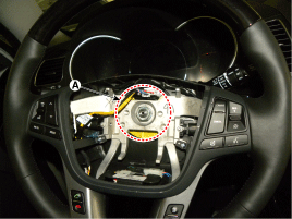
Disconnect the connector & lock nut (A) and then remove the steering
wheel by using special service tools (09561-11001).
|

| 5. |
Remove the steering column shroud.
(Refer to Restraint - "Driver Airbag (DAB) Module and Clock Spring")
|
| 6. |
Remove the clock spring.
(Refer to Restraint - "Driver Airbag (DAB) Module and Clock Spring")
|
| 7. |
Remove the multifunction switch.
(Refer to Body Electrical System - "Multifunction switch")
|
| 8. |
Remove the crash pad lower panel.
(Refer to Body (Interior and Exterior) - "Crash Pad Lower Panel")
|
| 9. |
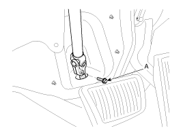
Loosen the bolt (A) and then disconnect the universal joint assembly
from the pinion of the steering gear box.
|
| 10. |
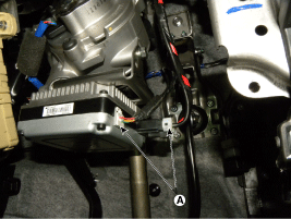
Disconnect all connectors (A) connected to the steering column.
|
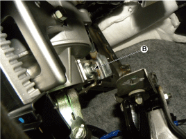
| 11. |
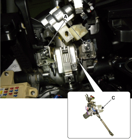
Remove the steering column (C) by loosening the mounting bolt
(B-1ea) and nut (A-2ea).
|
| 12. |
Install in the reverse order of removal.
|
| 13. |
Perform the steering angle sensor calibration.
(Refer to Electric Power Steering - " Repair procedures - ASP
Calibration")
|
 General Inspection
After or before servicing the EPS system, perform the troubleshooting
and test procedure as follows. Compare the system condition with normal condition
in the table below and if abnormal symp ...
 Steering Column and Shaft Disassembly
Universal joint assembly
1.
Loosen the bolt (A) and then disconnect the universal joint assembly
from the steering column assembly.
Tightenin ...
See also:
Overhead Console Lamp Removal
1.
Disconnect the negative (-) battery terminal.
2.
Remove the mounting screws (2EA).
And then remove the overhead console (A).
...
Front Strut Assembly Disassembly
1.
Remove the dust cover(A).
2.
Using the special tool (09546-26000), compress the coil spring
(A).
3.
...
Exterior overview
1. Hood
2. Head lamp
3. Fog lamp
4. Wheel and tire
5. Outside rearview mirror
6. Panorama sunroof
7. Front windshield wiper blades
8. Windows
9. Door locks
10. Fuel filler lid
11. Rear c ...
Categories
- Home
- First Generation
- Second Generation
- Kia Sorento XM 2011-2026 Owners Manual
- Kia Sorento XM 2011-2026 Service Manual

Copyright © www.ksmanual.com 2014-2026