 Kia Sorento: Starter Disassembly
Second Generation XM (2011-2026) / Kia Sorento XM 2011-2026 Service Manual / Engine Electrical System / Starting System / Starter Disassembly
| 1. |
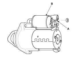
Disconnect the M-terminal (A) on the magnet switch assembly (B).
|
| 2. |
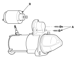
After loosening the screws (A), detach the magnet switch assembly
(B).
|
| 3. |
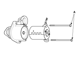
Loosen the through bolts (A).
|
| 4. |
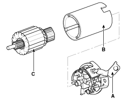
Remove the brush holder assembly (A), yoke (B) and armature (C).
|
| 5. |
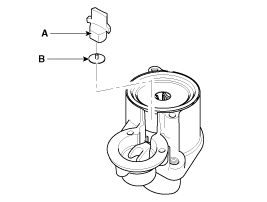
Remove the lever plate (B) and lever packing (A).
|
| 6. |
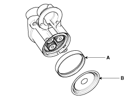
Remove the packing (A) and shield (B).
|
| 7. |
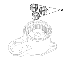
Disconnect the planet gear (A).
|
| 8. |
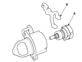
Disconnect the planet shaft assembly (or reducer assembly) (A)
and lever (B).
|
| 9. |
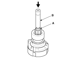
Press the stopper (A) using a socket (B).
|
| 10. |
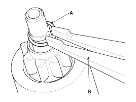
After removing the stop ring (A) using stop ring pliers (B).
|
| 11. |
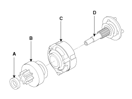
Disconnect the stopper (A), overrunning clutch (B), internal gear
(C), planet shaft (D) and/or gasket sheet (E).
|
| 12. |
Reassembly is the reverse of disassembly.
|
 Starter Installation
1.
Install in the reverse order of removal.
Starter installation bolt:
49.0 ~ 63.7 N.m (5.0 ~ 6.5 kgf.m, 36.2 ~ 47.0 lb-ft)
...
 Starter Reassembly
1.
Reassemble in the reverse order of disassembly.
...
See also:
Ignition Coil Circuit Diagram
...
Front Hub / Knuckle / Tone Wheel Removal and Installation
1.
Remove the front wheel and tire (A) from front hub .
Tightening torque:
88.2 ~ 107.8 N.m (9.0 ~ 11.0 kgf.m, 65.0 ~ 79.5 lb-ft)
...
Parking Brake Assembly Removal
Parking Brake Shoe
1.
Raise the vehicle, and make sure it is securely supported.
2.
Remove the rear tire and wheel.
3.
...
Copyright ® www.ksmanual.com 2014-2026

