 Kia Sorento: Start/Stop Button Removal
Second Generation XM (2011-2025) / Kia Sorento XM 2011-2025 Service Manual / Body Electrical System / Button Engine Start System / Start/Stop Button Removal
| 1. |
Disconnect the negative(-) battery terminal.
|
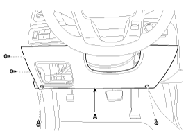
| 2. |
Remove the crash pad lower panel (A).
(Refer to Body - "Crash pad")
|
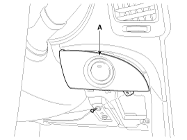
| 3. |
Remove the start/stop button cover (A) after loosening the mounting
screw.
|
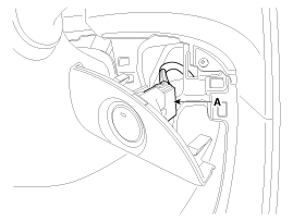
| 4. |
Disconnect the connector (A).
|
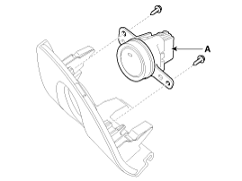
| 5. |
Remove the start/stop button (A) after loosening the mounting
screws.
|
 Start/Stop Button Installation
1.
Install the start/stop button.
2.
Install the start/stop button cover.
3.
Install the crash pad lower panel. ...
See also:
Side Impact Sensor (SIS) Removal
Front Side Impact Sensor
ŌĆó
Removal of the airbag must be performed according to ...
Power Seat Control Switch Installation
1.
Install the power seat control switch after connecting the connector.
...
Instrument cluster
1. Tachometer
2. Speedometer
3. Engine coolant temperature gauge
4. Fuel gauge
5. LCD display
6.Warning and indicator lights (if equipped)
7. Turn signal indicator lights
Instrument Cluster ...
Copyright ® www.ksmanual.com 2014-2025


