Kia Sorento: Shift Lever Removal and Installation - Automatic Transaxle Control System - Automatic Transaxle SystemKia Sorento: Shift Lever Removal and Installation

Kia Sorento (MQ4, 2021-2026) Service Manual / Automatic Transaxle System / Automatic Transaxle Control System / Shift Lever Removal and Installation

Removal
1.
Shift the shift lever to the N range.
Note
Use wheel chocks to prevent vehicle moved accidentally.
2.
Disconnect the battery negative ( - ) terminal.
3.
Remove the floor console assembly.
(Refer to Body - "Floor Console Assembly")
4.
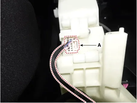
Disconnect the main connector (A).

Automatic Transaxle System — Automatic Transaxle Control System / Shift Lever / Removal and Installation / Removal illustration

5.
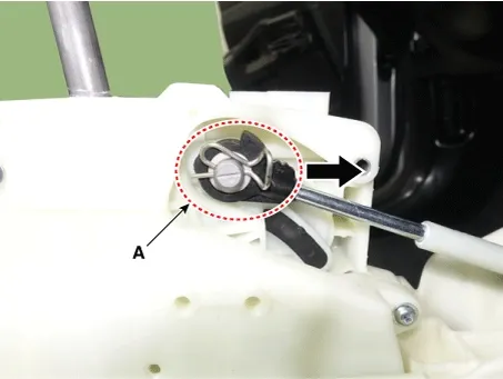
Remove the snap pin (A).

Automatic Transaxle System — Automatic Transaxle Control System / Shift Lever / Removal and Installation / Removal illustration

6.
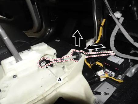
Remove the shift cable (A) from the shift lever.

Automatic Transaxle System — Automatic Transaxle Control System / Shift Lever / Removal and Installation / Removal illustration

7.
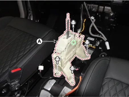
Remove the shift lever assembly (A).

Tightening torque :
8.8 - 13.7 N·m (0.9 - 1.4 kgf·m, 6.5 - 10.1 lb·ft)

Automatic Transaxle System — Automatic Transaxle Control System / Shift Lever / Removal and Installation / Removal illustration

Installation
1.
Install in the reverse order of removal.
Note
•
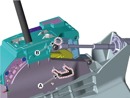
Before installing the shift cable, insert "N range fixing pin"(A) of shift lever after checking the shift lever and manual control lever are on "N" range.
•
Install the shift cable after checking the direction of projection (B) to prevent incorrect assembly.

Automatic Transaxle System — Automatic Transaxle Control System / Shift Lever / Removal and Installation / Installation illustration

•
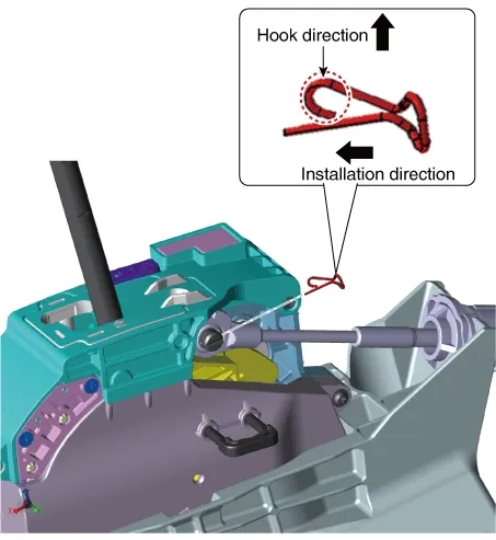
Mind the installation direction of snap pin and install the snap pin with the hook facing upward.

Automatic Transaxle System — Automatic Transaxle Control System / Shift Lever / Removal and Installation / Installation illustration

•
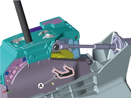
Make sure to get rid of "N range fixing pin"(A) after installing the shift lever assembly.

Automatic Transaxle System — Automatic Transaxle Control System / Shift Lever / Removal and Installation / Installation illustration

2.
Operate the shift lever to check whether each position (P, R, N, D) works.
Shift Lever Components and Components Location

Component 1. Manual Lever Assembly1-a. 8.8 - 13.7 N·m (0.9 - 1.4 kgf·m, 6.5 - 10.1 lb·ft) 2. Snap Pin3. Shift Cable Assembly...
Shift Cable Components and Components Location
Component 1. Shift Lever Knob & Boots 2. Shift Lever Assembly 3. Shift Cable Assembly3-a. 11.7 - 14.7 N·m (1.2 - 1.5 kgf·m, 8.6 - 10.8...
See also:

Direct Electro Hydraulic Actuator Coupling Repair procedures
Inspection ...

Valve Body Installation
Installation 1. Install in the reverse order of removal. ...

Illuminated ENGINE START/STOP button. ENGINE START/STOP button position
Illuminated ENGINE START/STOP button The backlight indicator on the start button auto ...

Copyright © www.ksmanual.com 2014-2026 - 0.0558