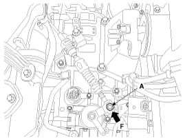
 Kia Sorento: Shift Cable Adjustment
Second Generation XM (2011-2024) / Kia Sorento XM 2011-2024 Service Manual / Automatic Transaxle System / Automatic Transaxle Control System / Shift Cable Adjustment
| Adjusting method for T/M control cable |
| 1. |
Set room side shift lever and T/M side manual control lever to
"N" position.
|
| 2. |
Connect room side shift lever and shift cable.
|
| 3. |
Push cable to "F" direction shown to eliminate FREE PLAY.
|
| 4. |
Tighten adjusting nut (A).
|
| 5. |
After adjusting according check to be sure that this part operates
surely at each range of T/M side corresponding to each position of shift
lever.
|
 Shift Cable Installation
1.
Install in the reverse order of removal.
Set shift lever and inhibitor ...
See also:
Compressor Removal
1.
If the compressor is marginally operable, run the engine at idle
speed, and let the air conditioning work for a few minutes, then shut
the engine off.
...
Rear Hub - Carrier Inspection
1.
Check the hub for cracks and the splines for wear.
2.
Check the rear axle carrier for cracks.
...
High Mounted stop lamp Installation
1.
Install the high mounted stop lamp.
2.
Install the tailgate trim.
...
Copyright В© www.ksmanual.com 2014-2024


