
 Kia Sorento: Removal
| Special Service Tool |
|
Tool Name / Number |
Illustration |
Description |
| Engine support fixture (bar) 09200 - 3N000 |
|
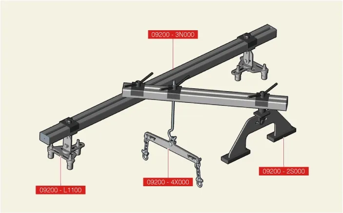
Used for holding engine assembly when removing / installing transaxle ※Refer to the engine support fixture assembly drawing below |
|
Engine support fixture (rear supporter) 09200 - L1100 |
|
Used for holding engine assembly when removing / installing transaxle ※Refer to the engine support fixture assembly drawing below |
| Engine support fixture (supporter) 09200 - 2S000 09200 - 2S100 |
|
Used for holding engine assembly when removing / installing transaxle ※Refer to the engine support fixture assembly drawing below |
| Engine support fixture (adapter) 09200 - 4X000 |
|
Used for holding engine assembly when removing / installing transaxle ※Refer to the engine support fixture assembly drawing below |
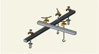
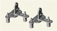
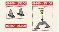
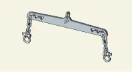
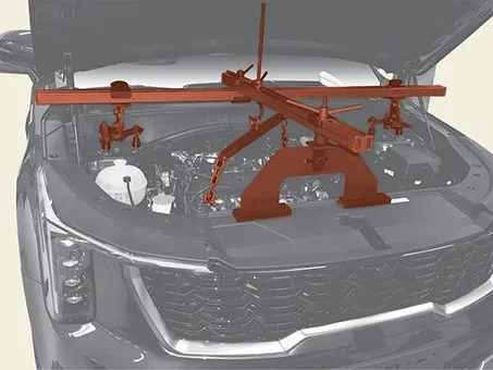
Engine support fixture assembly drawing
| Removal |
| 1. |
Remove the air cleaner assembly.
(Refer to Engine Mechanical System - "Air Cleaner")
|
| 2. |
Remove the battery and battery tray.
(Refer to Engine Electrical System - "Battery")
|
| 3. |
Drain the engine coolant.
(Refer to Engine Mechanical System - "Coolant")
|
| 4. |
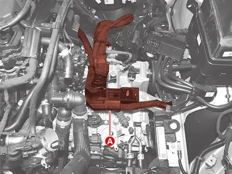
Separate the main wiring protector (A) from the body frame.
|
| 5. |
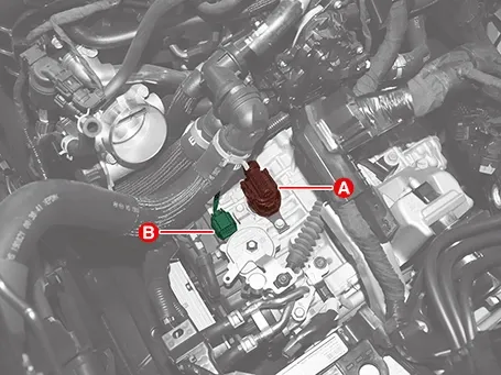
Disconnect the main connector (A) and position switch connector (B).
|
| 6. |
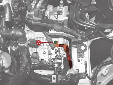
Remove the ground cable (A) after removing the bolt.
|
| 7. |
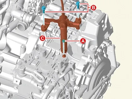
Remove the shift cable (C) after removing the nut (A) and bolts (B).
|
| 8. |
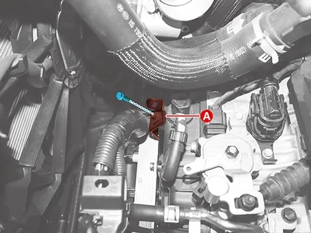
Remove the wiring bracket (A) after removing the bolt.
|
| 9. |
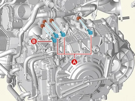
Remove the transaxle upper mounting bolts (A) and starter mounting bolt (B).
|
| 10. |
Assemble the engine support fixture on the engine room.
(Refer to Special Service Tools - "Engine support fixture assembly
drawing")
|
| 11. |
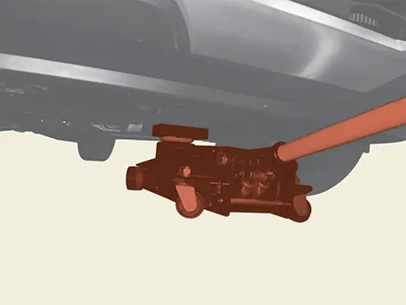
Support the transaxle with a jack.
|
| 12. |
Remove the left side front wheel guard.
(Refer to body - "Front Wheel Guard")
|
| 13. |
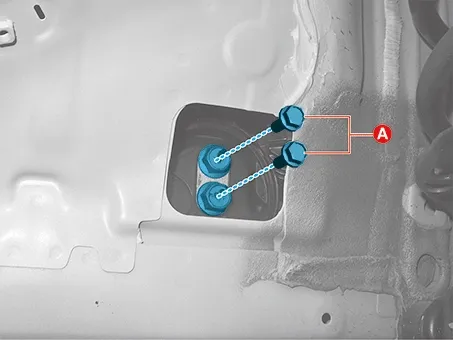
Remove the transaxle mounting bracket bolts (A).
|
| 14. |
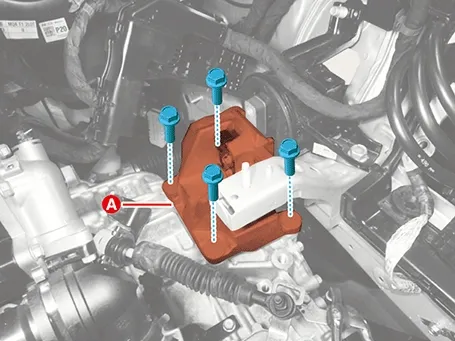
Remove the transaxle support bracket (A).
|
| 15. |
Remove the driveshaft assembly.
(Refer to Driveshaft and Axle - "Front Driveshaft")
|
| 16. |
Remove the front sub frame.
(Refer to Suspension System - "Front Sub Frame")
|
| 17. |
Remove the transfer assembly. [AWD only]
(Refer to ALL Wheel Drive System - "Front Wheel Transfer
Assembly")
|
| 18. |
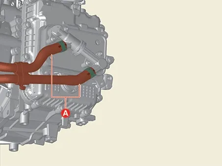
Separate the coolant hoses (A).
|
| 19. |
Remove the roll rod support bracket (A).
|
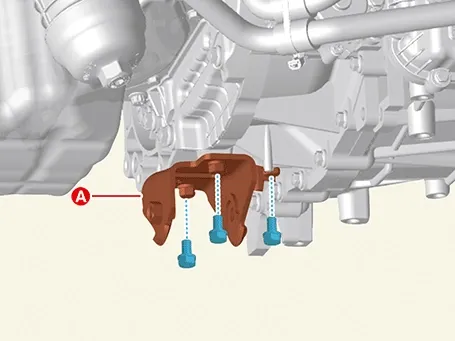
| 20. |
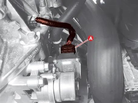
Disconnect the electric oil pump connector (A).
|
| 21. |
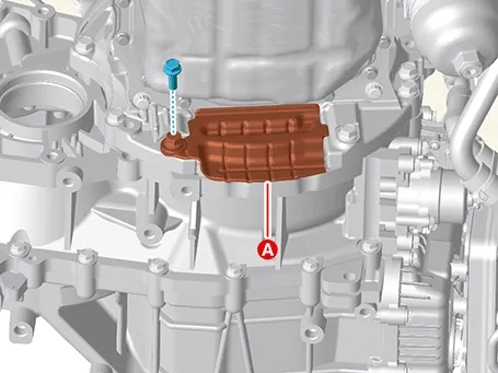
Remove the dust cover (A).
|
| 22. |
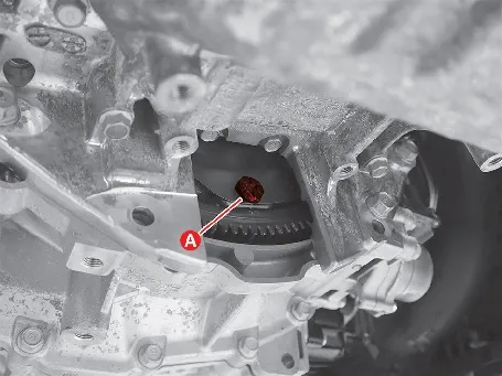
Remove the torque converter mounting bolts (A) by rotating the crankshaft in the clockwise.
|
| 23. |
Support the transaxle safely with a jack.
|
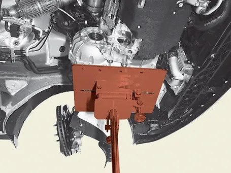
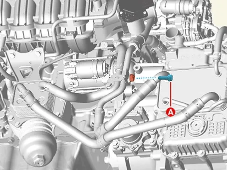
| 24. |
Remove the starter mounting bolt (A).
|
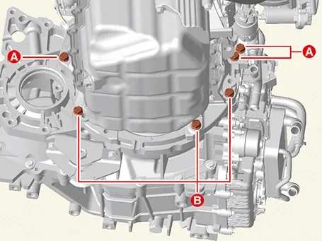
| 25. |
Remove the transaxle lower mounting bolts (A, B).
|
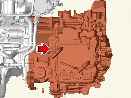
| 26. |
After separating the transaxle from the engine, remove the transaxle by lowering the jack slowly.
|

Component
1. Automatic Transaxle Support Braket1-a. 58.9 -
78.5 N·m (6.0 - 8.0 kgf·m, 43.4 - 57.9 lb·ft) 1-b. 107.9 - 127.5 N·m (11.0 - 13.0 kgf·m, 79....
 Components and Components Location
Special Service Tool
Tool Name / Number
Illustration
Description
Oil seal installer09452 - 26100
...
 Installation
See also:
Power Door Mirror Actuator Repair Procedures
Inspection
1.
Remove the front door trim.
(Refer to Body - "Front Door Trim")
[Mirror ...
Engine coolant. Checking the coolant level
Your Kia Sorento is equipped with a high-pressure cooling system that utilizes a reservoir pre-filled at the factory with year-round antifreeze coolant. This system is designed to maintain consistent ...
Removal
1.
Turn the ignition switch OFF and disconnect the battery negative
(-) cable.
2.
Remove the rear seat.
(Refer to Body - "Rear ...
Manuals list
- Kia Sorento MQ4 2021-2026 Owners Manual
- Kia Sorento XM 2011-2015 Owners Manual
- Kia Sorento XM 2011-2015 Service Manual

Copyright © www.ksmanual.com 2014-2026 - 0.0483