Kia Sorento: Power Door Look Module Repair Procedures - Power Door Locks and Burglar alarm - Body Electrical SystemKia Sorento: Power Door Look Module Repair Procedures

Kia Sorento (MQ4, 2021-2026) Service Manual / Body Electrical System / Power Door Locks and Burglar alarm / Power Door Look Module Repair Procedures

Inspection
Front Door Lock Module
1.
Remove the front door module.
(Refer to Body - "Front Door Module")
2.
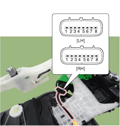
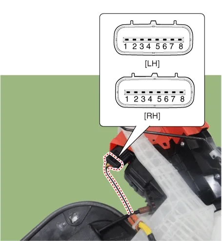
Disconnect the connector from the door lock module.

Body Electrical System — Power Door Locks and Burglar alarm / Power Door Look Module / Repair Procedures / Inspection illustration

Terminal
Function
LH
RH
1
-
M2
2
-
M3
3
COM
-
4
Lock / Unlock switch
AJAR
5
AJAR
Lock / Unlock switch
6
-
COM
7
M3
-
8
M2
-

3.
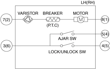
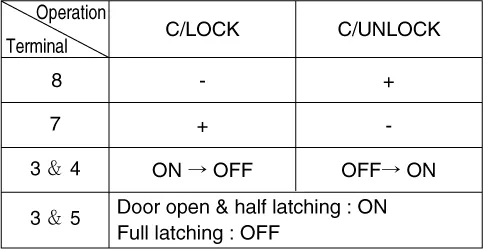
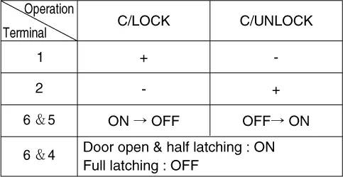
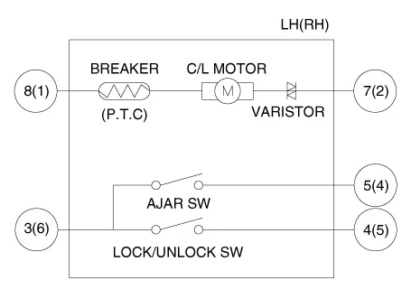
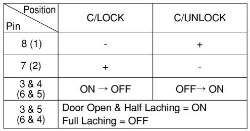
Apply battery voltage to each terminal as shown in the table below and check whether it operates properly.

Body Electrical System — Power Door Locks and Burglar alarm / Power Door Look Module / Repair Procedures / Inspection illustration

LH

Body Electrical System — Power Door Locks and Burglar alarm / Power Door Look Module / Repair Procedures / Inspection illustration

RH

Body Electrical System — Power Door Locks and Burglar alarm / Power Door Look Module / Repair Procedures / Inspection illustration

Rear Door Lock Module
1.
Remove the rear door module.
(Refer to Body - "Rear Door Module")
2.
Disconnect the connector from the door lock module.

Body Electrical System — Power Door Locks and Burglar alarm / Power Door Look Module / Repair Procedures / Inspection illustration

Terminal
Function
LH
RH
Central Lock
Power Child Lock
Central Lock
Power Child Lock
1
-
Power child switch
M2
M1
2
-
COM
M3
M2
3
COM
Lock / Unlock switch
-
M3
4
Lock / Unlock switch
Switch (AJAR)
Switch (AJAR)
M4
5
Switch (AJAR)
M4
Lock / Unlock switch
Switch (AJAR)
6
-
M3
COM
Lock / Unlock switch
7
M3
M2
-
COM
8
M2
M1
-
Power child switch

3.
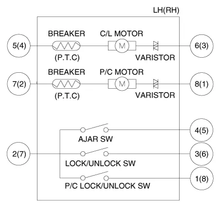
Apply battery voltage to each terminal as shown in the table below and check whether it operates properly.
[Central Lock]

Body Electrical System — Power Door Locks and Burglar alarm / Power Door Look Module / Repair Procedures / Inspection illustration

[Power Child Lock]

Body Electrical System — Power Door Locks and Burglar alarm / Power Door Look Module / Repair Procedures / Inspection illustration

[Central Lock]

Body Electrical System — Power Door Locks and Burglar alarm / Power Door Look Module / Repair Procedures / Inspection illustration

[Power Child Lock]

Body Electrical System — Power Door Locks and Burglar alarm / Power Door Look Module / Repair Procedures / Inspection illustration

Tailgate Lock Module
1.
Remove the tailgate trim.
(Refer to Body - "Tailgate Trim")
2.
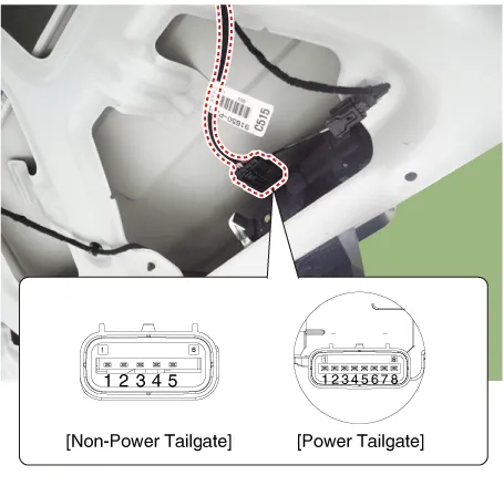
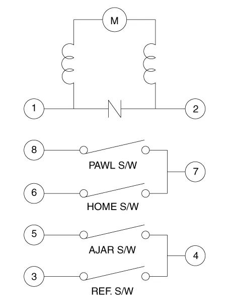
Disconnect the tailgate lock module connector.

Body Electrical System — Power Door Locks and Burglar alarm / Power Door Look Module / Repair Procedures / Inspection illustration

Terminal
Function
Non-Power Tailgate
Power Tailgate
1
Motor ( + )
Motor ( - )
2
Open switch
Motor ( + )
3
Motor ( - )
Switch (REF)
4
Ground
COM
5
Lock switch
Switch (AJAR)
6
-
Switch (HOME)
7

COM
8
PAWL switch

3.
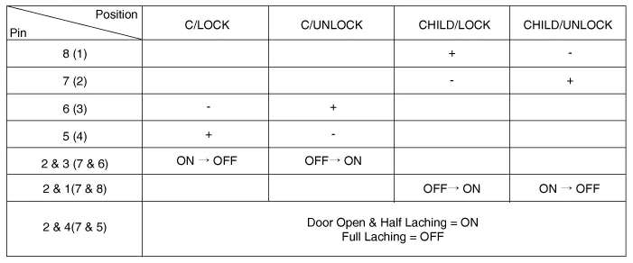
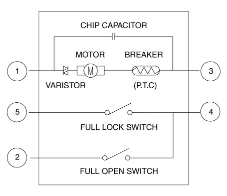
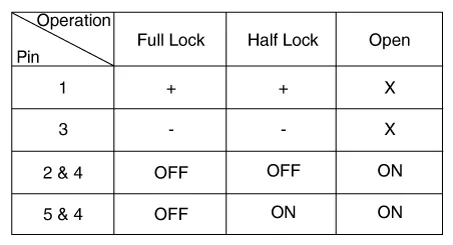
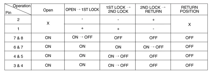
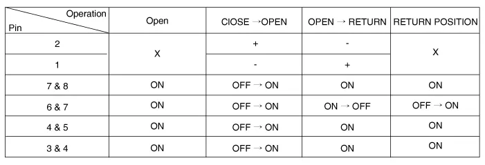
Apply battery voltage to each terminal as shown in the table below and check whether it operates properly.
[Non-Power Tailgate]

Body Electrical System — Power Door Locks and Burglar alarm / Power Door Look Module / Repair Procedures / Inspection illustration

Body Electrical System — Power Door Locks and Burglar alarm / Power Door Look Module / Repair Procedures / Inspection illustration

[Power Tailgate]

Body Electrical System — Power Door Locks and Burglar alarm / Power Door Look Module / Repair Procedures / Inspection illustration

1) Lock

Body Electrical System — Power Door Locks and Burglar alarm / Power Door Look Module / Repair Procedures / Inspection illustration

2) Open

Body Electrical System — Power Door Locks and Burglar alarm / Power Door Look Module / Repair Procedures / Inspection illustration

Hood Lock Module
1.
Remove the front bumper assembly.
(Refer to Body - "Front Bumper Assembly")
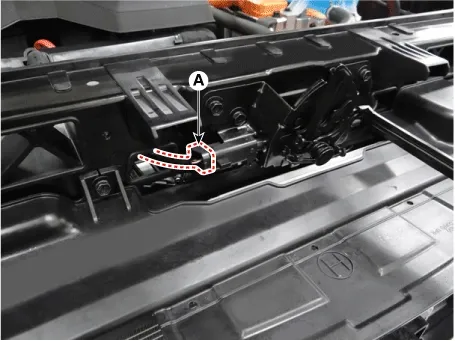
2.
Disconnect the hood latch connector (A).

Body Electrical System — Power Door Locks and Burglar alarm / Power Door Look Module / Repair Procedures / Inspection illustration

3.
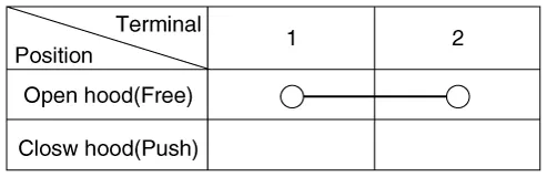
Check for continuity between terminals No. 1 and No. 2. If there is no continuity, replace the hood latch switch.

Body Electrical System — Power Door Locks and Burglar alarm / Power Door Look Module / Repair Procedures / Inspection illustration

Burglar Alarm
1.
Disconnect the battery negative ( - ) terminal.
2.
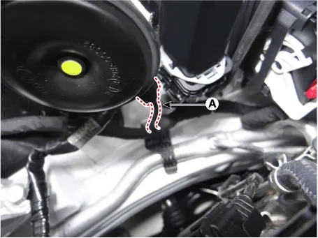
Disconnect the burglar alarm connector (A).

Body Electrical System — Power Door Locks and Burglar alarm / Power Door Look Module / Repair Procedures / Inspection illustration

3.
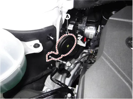
Remove the burglar alarm horn (A) after removing the bolt.

Body Electrical System — Power Door Locks and Burglar alarm / Power Door Look Module / Repair Procedures / Inspection illustration

4.
Apply battery voltage to connector terminal and check that the burglar alarm operates properly.
Removal
Front Door Lock Module
1.
Remove the front door latch.
(Refer to Body - "Front Door Latch")
Rear Door Lock Module
1.
Remove the rear door latch.
(Refer to Body - "Rear Door Latch")
Tailgate Lock Module
1.
Remove the tailgate latch.
(Refer to Body - "Tailgate Latch")
Hood Lock Module
1.
Remove the hood latch.
(Refer to Body - "Hood Latch Assembly")
Installation
1.
Install in the reverse order of removal.
Power Door Lock Switch On Vehicle Inspection. Power Door Lock Switch Repair Procedures

Power Door Lock Switch On Vehicle Inspection On Vehicle Inspection Diagnostic with KDS 1. The power doo...
Power Door Mirrors
...
See also:

Vehicle Stability Management (VSM) system. Trailer Stability Assist (TSA) system
Vehicle Stability Management (VSM) system The Vehicle Stability Management (VSM) system works in harmony with the Electronic Stability Control and Motor-Driven Power Steering to further enhance ...

Blind Spot Detection Unit Removal
1. Disconnect the negative (-) battery terminal. 2. Remove the rear bumper. (Refer to Body - "Rear Bumper") ...

Digital Key 2 (NFC Card Key)
How to Register Digital Key 2 (NFC Card Key) To pair a physical NFC smart card key with your Kia Sorento, complete the following vehicle programming sequence: Enter your Kia Sorent ...

Copyright © www.ksmanual.com 2014-2026 - 0.0471