
 Kia Sorento: Parking Brake Cable Repair procedures
Kia Sorento (MQ4, 2021-2026) Service Manual / Brake System / Parking Brake System / Parking Brake Cable Repair procedures
| Removal |
[Front]
| 1. |
Disconnect the (-) battery terminal.
|
| 2. |
Release the parking brake.
|
| 3. |
Remove the crash pad lower panel.
(Refer to Body - "Crash Pad Lower Panel")
|
| 4. |
Remove the Body Domain Control Unit.
(Refer to Body Electrical System - "Body Domain Control
Unit")
|
| 5. |
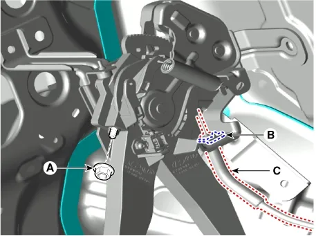
Separate the parking brake cable (C) by removing the nut (A) and retaining clip (B).
|
| 6. |
Remove the floor console assembly.
(Refer to Body - "Floor Console Assembly")
|
| 7. |
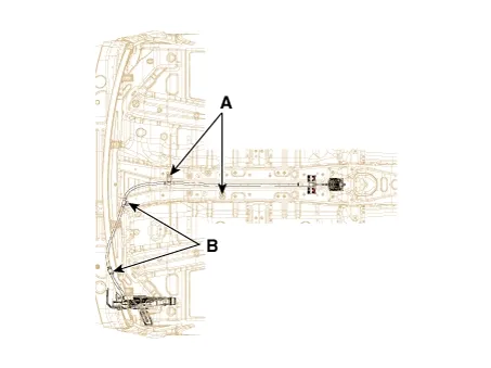
Remove the parking brake cable mounting bolts (A) and nuts (B).
|
| 8. |
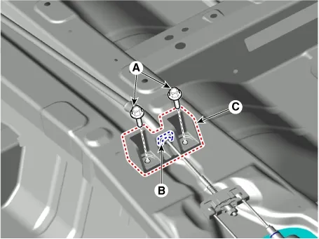
Remove the front parking brake cable bracket (C) by removing the bolts (A) and clip (B).
|
| 9. |
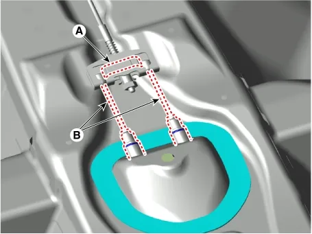
Remove the cable retainer (A) and remove the parking brake cable (B).
|
[Rear]
| 1. |
Disconnect the (-) battery terminal.
|
| 2. |
Release the parking brake.
|
| 3. |
Remove the cable retainer (A) and remove the parking brake cable (B).
|
| 4. |
Remove the rear wheel and tire.
(Refer to Suspension System - "Wheel")
|
| 5. |
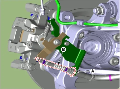
Remove the parking brake cable (B), after removing the clip (A).
|
| 6. |
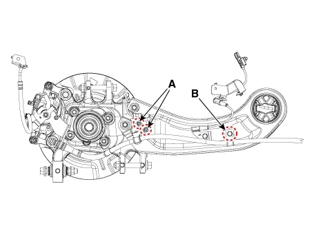
Remove the parking brake cable bracket mounting nuts (A) and bolt (B).
|
| 7. |
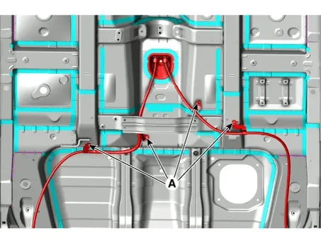
Remove the mounting bolts (A) and remove the parking brake cable.
|
| Installation |
| 1. |
Install in the reverse order of removal.
|
| 2. |
After the installation, check the operation status of the parking brake and brake switch.
|
| Adjustment |
After disassembling/assembling the caliper body or replacing the caliper, parking brake cable or brake
disc, re-adjust the parking brake.
|

| 1. |
Remove the floor console assembly.
(Refer to Body - "Floor Console Assembly")
|
| 2. |
To fit the cable, follow one of these procedures.
|
| 3. |
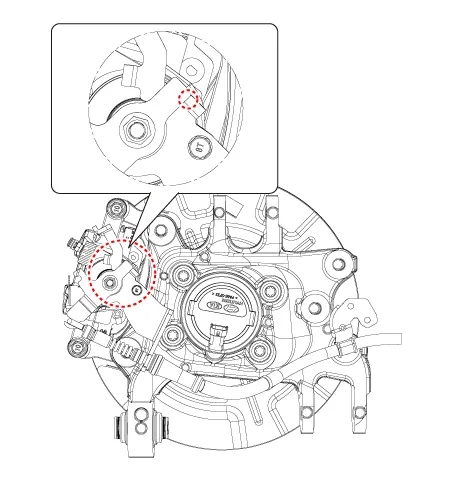
After fitting the cable, adjust the adjustment nut so that the stroke is 5 - 6 notch when operating the
pedal at 30kgf.
|
| 4. |
Make sure that there is no gap between adjustment nut and clip after adjusting the parking brake.
|
| 5. |
Make sure that the brakes are not drag.
|
| 6. |
Check whether the wheel operates smoothly.
|
| 7. |
Perform driving test.
|
| 8. |
Install the floor console assembly.
(Refer to Body - "Floor Console Assembly")
|
Removal
1.
Disconnect the (-) battery terminal.
2.
Release the parking brake.
...
 Parking Brake Pedal Assembly Repair procedures
Description
The EPB is an electronic parking brake.
The EPB is different from existing parking systems which operate with the brake pedal or the lever type. The EPB
system sends the...
 Electric Parking Brake (EPB) Description and Operation
See also:
Side Impact Sensor (SIS) Description
Side Impact Sensor (SIS) system consists of two Front-SIS which are installed
at each center of the front door module (LH and RH) and two Rear-SIS which are
installed at each rear pillar near ...
Auto Head lamp leveling Unit Removal
Height Sensor & Unit
1.
Disconnect the negative(-) battery terminal.
2.
Remove the height sensor connector (A).
...
Manuals list
- Kia Sorento MQ4 2021-2026 Owners Manual
- Kia Sorento XM 2011-2015 Owners Manual
- Kia Sorento XM 2011-2015 Service Manual

Copyright © www.ksmanual.com 2014-2026 - 0.0686