 Kia Sorento: MDPS Column and Housing Repair procedures
| 1. |
Align the steering wheel so that the front wheels to facing straight ahead.
|
If the steering wheel and the front tires does not synchronize to their centers together, open
circuit on the clock spring cable may occur due to change the steering wheel turning.
|
|
| 2. |
Disconnect the (-) battery terminal.
|
| 3. |
Remove the multifunction switch module.
(Refer to Body Electrical System - "Multifunction Switch")
|
| 4. |
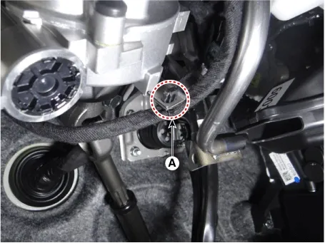
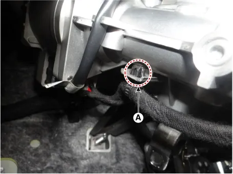
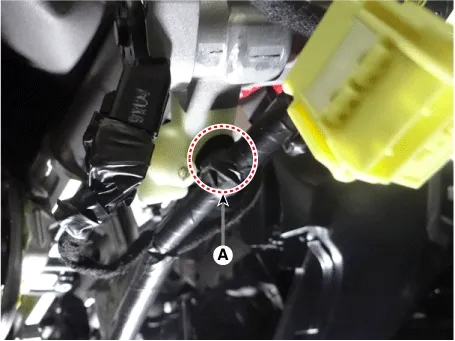
Remove the wiring fixed fasner (A) from the steering column.
|
| 5. |
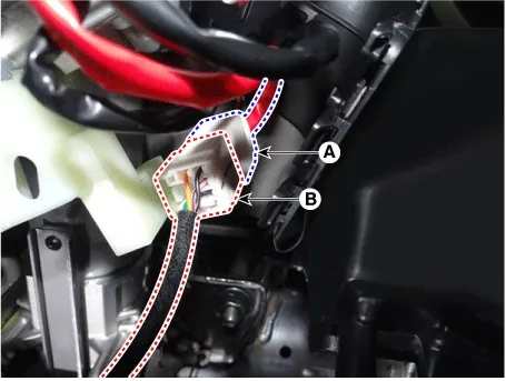
Disconnect the key lock assembly connector (A) from ECU connector (B).
|
| 6. |
Disconnect the key lock assembly connector (A).
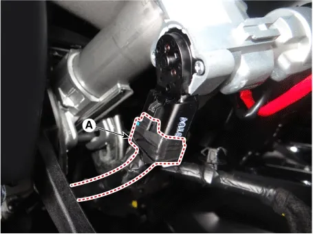
|
| 7. |
Disconnect the MDPS power pack assembly connectors (A).
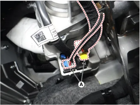
|
Disconnect the connector in the following order.
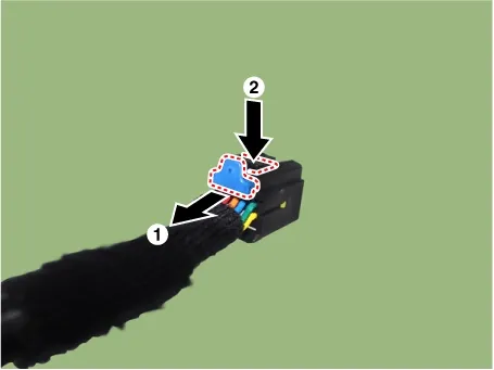
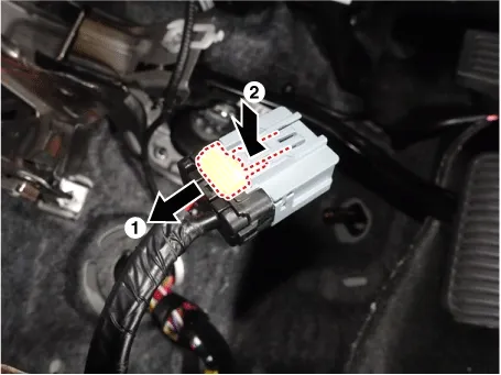
|
|
| 8. |
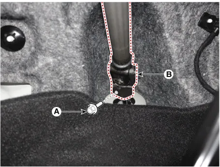
Loosen the bolt (A) and remove the universal joint (B).
Tightening torque :
49.0 - 58.8 N·m (5.0 - 6.0 kgf·m, 36.2 - 43.4 lb·ft)
|
|
•
|
Secure the steering wheel so that it does not move.
|
|
•
|
Lock the steering wheel in the straight ahead position to prevent the damage of the clock
spring inner cable.
|
|
|
| 9. |
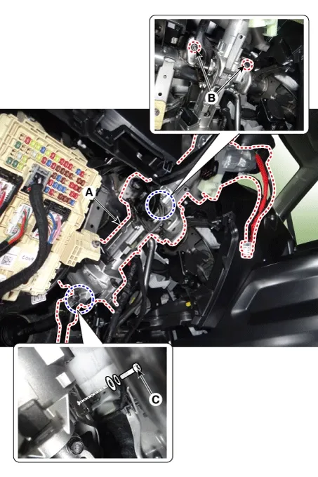
Remove the MDPS Column & Housing (A) after loosening the mounting nuts (B) and bolt (C).
Tightening torque
Nuts (B) : 25.0 - 29.4 N·m (2.5 - 3.0 kgf·m, 14.5 - 21.7 lb·ft)
Bolt (C) : 53.9 - 58.8 N·m (5.5 - 6.0 kgf·m, 39.8 - 43.4 lb·ft)
|
|
Universal Joint Assembly
| 1. |
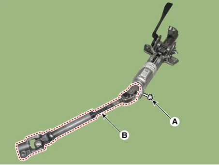
Loosen the bolt (A) to separate the steering column assembly and the universal joint assembly (B).
Tightening torque :
49.0 - 58.8 N·m (5.0 - 6.0 kgf·m, 36.2 - 43.4 lb·ft)
|
|
Key Lock Assembly
| 1. |
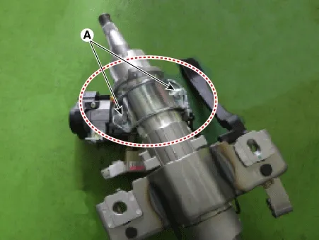
Make a groove on the head of special bolts (A) by a punch.
|
| 2. |
Loosen the special bolt using a screw driver and then remove the key lock assembly from the steering column
assembly.
|
| 1. |
Check the steering column for damage and deformation.
|
| 2. |
Check the joint bearing for damage and wear.
|
| 3. |
Check the tilt bracket for damage and cracks.
|
|
•
|
Install the component to the specified torque.
|
|
•
|
Assemble the steering universal joint by taking care of the groove so that it can be bolted.
|
|
| 1. |
Assemble in the reverse order of disassembly.
|
|
•
|
Install the component to the specified torque.
|
|
•
|
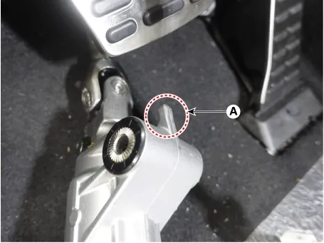
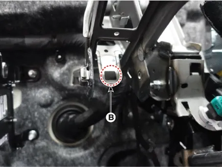
When assembling the MDPS assembly, insert the dowel pin (A) into the groove of the MDPS bracket
(B).
|
|
| 1. |
Install in the reverse order of removal.
|
| 2. |
Perform the "MDPS Tuning Data Setting" by KDS.
(Refer to MDPS System - "Diagnosis with KDS")
|
| 3. |
Perform the "SAS Calibration" and "Set the steering feel torque to zero" by KDS.
(Refer to MDPS System - "Diagnosis with KDS")
|
Inspection
1.
MDPS power pack assembly failure can be quickly diagnosed using the vehicle diagnostic system (KDS).
...
On Vehicle Inspection
1.
Check the universal joint bearing for damage or wear.
2.
Check whether...



 MDPS System Repair procedures
 Universal Joint Assembly On Vehicle Inspection
