Kia Sorento: Front Strut Assembly Repair procedures - Front Suspension System - Suspension SystemKia Sorento: Front Strut Assembly Repair procedures

Kia Sorento (MQ4, 2021-2026) Service Manual / Suspension System / Front Suspension System / Front Strut Assembly Repair procedures

Removal
1.
Disconnect the (-) battery terminal.
2.
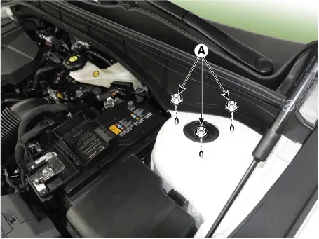
Remove the front strut upper mounting nuts (A).

Tightening torque :
53.9 - 68.6 N·m (5.5 - 7.5 kgf·m, 39.8 - 50.6 lb·ft)

Suspension System — Front Suspension System / Front Strut Assembly / Repair procedures / Removal illustration

3.
Remove the front wheel and tire.
(Refer to Tires/Wheels - "Wheel")
4.
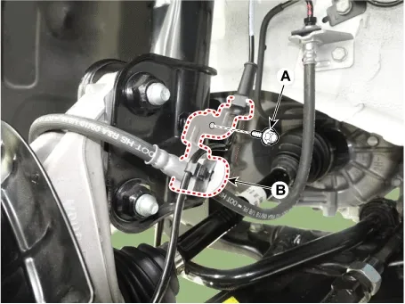
Remove the mounting bolt (A) and then remove the brake hose bracket (B) from the strut assembly.

Tightening torque :
12.7 - 16.6 N·m (1.3 - 1.7 kgf·m, 9.4 - 12.2 lb·ft)

Suspension System — Front Suspension System / Front Strut Assembly / Repair procedures / Removal illustration

5.
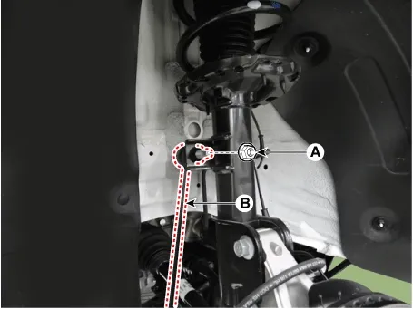
Disconnect the stabilizer bar link (B) with the front strut assembly after removing the nut (A).

Tightening torque :
98.1 - 117.7 N·m (10.0 - 12.0 kgf·m, 72.3 - 86.8 lb·ft)

Suspension System — Front Suspension System / Front Strut Assembly / Repair procedures / Removal illustration

Note
•
When removing the nut (A), fix the outer hexagon of stabilizer bar link.
•
Be careful not to damage the stabilizer bar link boots.
6.
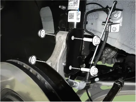
Remove the front strut assembly from the front axle by removing the bolts and nuts.

Tightening torque :
235.3 - 254.9 N·m (24.0 - 26.0 kgf·m, 173.5 - 188.0 lb·ft)

Suspension System — Front Suspension System / Front Strut Assembly / Repair procedures / Removal illustration

Disassembly
Information
•
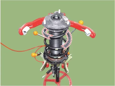
When compressing the coil spring, be cautious as there may be corrosion due to damage to the coil spring painting. In order to avoid such painting damage, compress by putting over a piece of plastic hose, etc. (Refer to the picture below.)

Suspension System — Front Suspension System / Front Strut Assembly / Repair procedures / Disassembly illustration

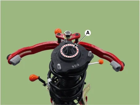
1.
Remove the insulator dust cover (A).

Suspension System — Front Suspension System / Front Strut Assembly / Repair procedures / Disassembly illustration

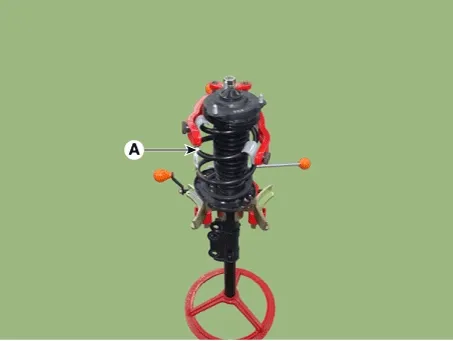
2.
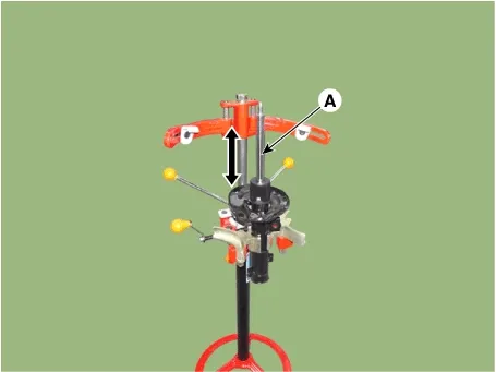
Using the spring compressor, compress the coil spring (A).
Do not compress the spring more than necessary.

Suspension System — Front Suspension System / Front Strut Assembly / Repair procedures / Disassembly illustration

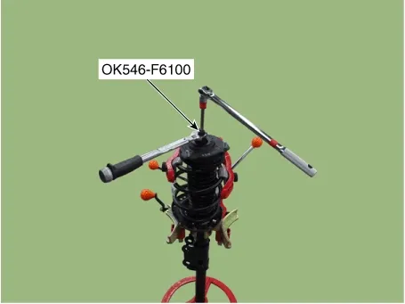
3.
Using SST (0K546-F6100), Remove the self locking nut.

Suspension System — Front Suspension System / Front Strut Assembly / Repair procedures / Disassembly illustration

4.
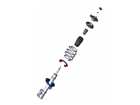
Remove the insulator, spring pad, coil spring and dust cover from the strut assembly.

Suspension System — Front Suspension System / Front Strut Assembly / Repair procedures / Disassembly illustration

Inspection
1.
Check the strut bearing for wear and damage.
2.
Check the spring upper and lower seat for damage and deterioration.
3.
Compress and extend the piston rod (A) and check that there is no abnormal resistance or unusual sound during operation.

Suspension System — Front Suspension System / Front Strut Assembly / Repair procedures / Inspection illustration

Disposal
1.
Fully extend the piston rod.
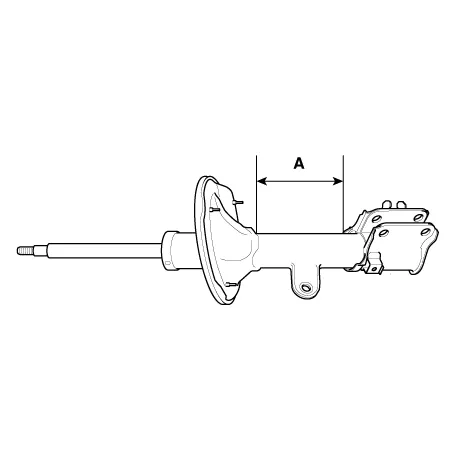
2.
Drill a hole on the A section to remove gas from the cylinder in section (A).

Suspension System — Front Suspension System / Front Strut Assembly / Repair procedures / Disposal illustration

Caution
•
The gas coming out is harmless, but be careful of chips that may fly when drilling.
•
Be sure to wear safety goggles or eye protection when performing this task.
Reassembly
1.
Install the insulator, spring pad, coil spring and dust cover from the strut assembly.
Caution
•
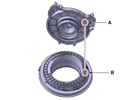
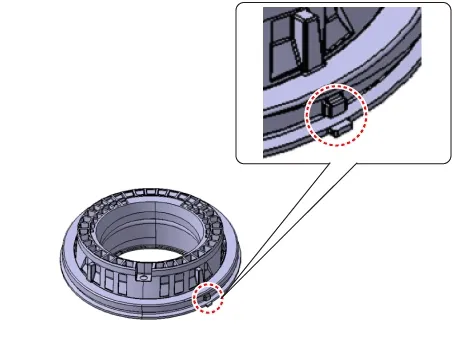
When install the insulator and strut bearing align the insulator lug (A) with the sturt bearing hole (B).

Suspension System — Front Suspension System / Front Strut Assembly / Repair procedures / Reassembly illustration

•
Align the strut upper housing with the lower housing lug and than installing.

Suspension System — Front Suspension System / Front Strut Assembly / Repair procedures / Reassembly illustration

2.
Compress and extend the piston rod (A) and check that there is no abnormal resistance or unusual sound during operation.

Suspension System — Front Suspension System / Front Strut Assembly / Repair procedures / Reassembly illustration

3.
Using the special tool (0K546-F6100), install the self locking nut.
Note
Do not reuse the self locking nut.

Tightening torque :
107.8 - 117.7 N·m (11.0 - 12.0 kgf·m, 79.6 - 86.8 lb·ft)

Suspension System — Front Suspension System / Front Strut Assembly / Repair procedures / Reassembly illustration

4.
Install the insulator cap (A).

Suspension System — Front Suspension System / Front Strut Assembly / Repair procedures / Reassembly illustration

Installation
1.
Install in the reverse order of removal.
Components and Components Location. Front Strut Assembly Components and Components Location

Components and Components Location Components 1. Front strut assembly2. Front axle assembly3. Front lower arm4. Steering gear box5. Stabil...
Front Lower Arm Repair procedures
Removal 1. Disconnect the (-) battery terminal. 2. Remove the front wheel and tire. (Re...
See also:

Rear Oil Seal Removal
1. Remove the automatic transaxle. (Refer to Automatic Transaxle System - "Automatic Transaxle") 2. Remove the drive plate. ...

Component Location
1. Driver power window main switch 2. Passenger window switch 3. Front window motor 4. Rear window motor 5. Rear window switch ...

Specifications
Description Specifications Limit General Type In-line, DOHC   Number of cylinders 4   ...

Copyright © www.ksmanual.com 2014-2026 - 0.0524