Kia Sorento: Front Hub Assembly Repair procedures - Front Axle Assembly - Driveshaft and axleKia Sorento: Front Hub Assembly Repair procedures

Kia Sorento (MQ4, 2021-2026) Service Manual / Driveshaft and axle / Front Axle Assembly / Front Hub Assembly Repair procedures

Removal
1.
Disconnect the (-) battery terminal.
2.
Remove the front wheel and tire.
(Refer to Suspension System - "Wheel")
3.
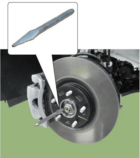
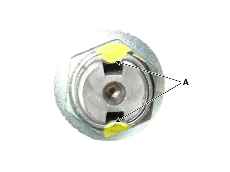
By hammering on a chisel, unlock the driveshaft lock hub nut caulking.

Driveshaft and axle — Front Axle Assembly / Front Hub Assembly / Repair procedures / Removal illustration

Note
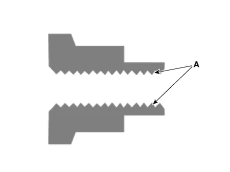
If there is screw thread (A) on the end of the nut, unlock the caulking by using a chisel and then remove the nut to prevent damaging driveshaft screw thread.

Driveshaft and axle — Front Axle Assembly / Front Hub Assembly / Repair procedures / Removal illustration

4.
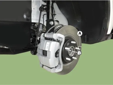
Remove the caulking nut (A) from the front axle.

Tightening torque :
294.2 - 313.8 N·m (30.0 - 32.0 kgf·m, 217.0 - 231.5 lb·ft)

Driveshaft and axle — Front Axle Assembly / Front Hub Assembly / Repair procedures / Removal illustration

Note
•
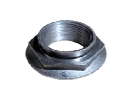
The driveshaft lock nut must be replaced with new one. When replacing the drive lock hub nut, use only the nut with screw thread (A) on the end.

Driveshaft and axle — Front Axle Assembly / Front Hub Assembly / Repair procedures / Removal illustration

•
When replacing the drive lock hub nut, use only the nut with screw thread (A) on the end.

Driveshaft and axle — Front Axle Assembly / Front Hub Assembly / Repair procedures / Removal illustration

•
Tighten the driveshaft lock hub nut to the specified tightening torque, and caulk by using a chisel and hammer.
•
If there are two key seats, perform on all two seats.

Caulking depth (A) : 1.5 mm (0.0591 in)

Driveshaft and axle — Front Axle Assembly / Front Hub Assembly / Repair procedures / Removal illustration

5.
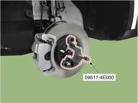
Disconnect the driveshaft from the axle hub by using the SST (09517-4E000).

Driveshaft and axle — Front Axle Assembly / Front Hub Assembly / Repair procedures / Removal illustration

Note
Removing the driveshaft, do not force pull or over deflect the axle.
6.
Remove the front brake disc.
(Refer to Brake System - "Front Brake Disc")
7.
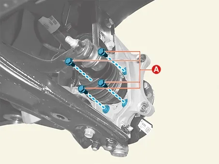
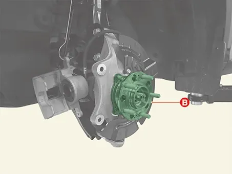
Remove the bolts and remove the hub bearing assembly (A) from the front knuckle.

Tightening torque :
127.5 - 147.1 N·m (13.0 - 15.0 kgf·m, 94.0 - 108.5 lb·ft)

Driveshaft and axle — Front Axle Assembly / Front Hub Assembly / Repair procedures / Removal illustration

Driveshaft and axle — Front Axle Assembly / Front Hub Assembly / Repair procedures / Removal illustration

Installation
1.
Install in the reverse order of removal.
Front Axle Assembly Repair procedures

Removal 1. Disconnect the (-) battery terminal. 2. Remove the front wheel and tire. (Re...
Rear Axle Assembly
...
See also:

Auto Defogging Sensor Removal and Installation
Removal 1. Remove the multi-sensor blanking cover (A). ...

Electrical Exhaust Gas Recirculation (E-EGR) Valve Specifications. Electrical Exhaust Gas Recirculation (E-EGR) Valve Description and Operation
Electrical Exhaust Gas Recirculation (E-EGR) Valve Specifications Specification [Motor] Item Specification ...

Tire replacement
If the tire is worn evenly, a tread wear indicator will appear as a solid band across the tread. This shows there is less than 1/16 inch (1.6 mm) of tread left on the tire. Replace the tire when t ...

Copyright © www.ksmanual.com 2014-2026 - 0.0528