 Kia Sorento: Front Axle Assembly Repair procedures
| 1. |
Disconnect the (-) battery terminal.
|
| 2. |
Remove the front wheel and tire.
(Refer to Suspension System - "Wheel")
|
| 3. |
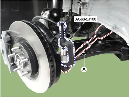
Disconnect the tie rod end ball joint from the knuckle by using the SST (09568-2J100).
| (1)
|
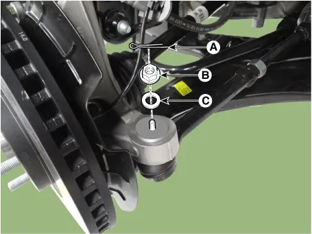
Remove the split pin (A).
|
| (2)
|
Remove the lock nut (B) and washer (C).
Tightening torque :
98.1 - 117.7 N·m (10.0 - 12.0 kgf·m, 72.3 - 86.8 lb·ft)
|
|
Do not reuse mounting nut.
|
|
| (3)
|
Disconnect the tie rod end ball joint from the knuckle by using the SST (09568-2J100).
|
|
| 4. |
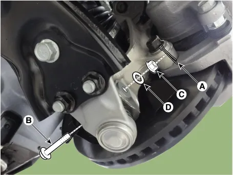
Remove the lower arm mounting nut (A).
| (1)
|
Remove the split pin (A).
|
| (2)
|
Remove the lower arm mounting bolt (B), nut (C) and washer (D).
Tightening torque :
98.1 - 117.7 N·m (10.0 - 12.0 kgf·m, 72.3 - 86.8 lb·ft)
|
|
To remove the nut (C), fix the bolt (B) on the opposite side to prevent it from turning.
|
|
|
| 5. |
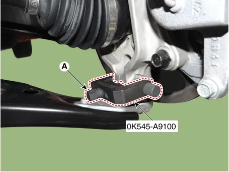
Disconnect lower arm ball joint from the knuckle by using the SST (0K545-A9100).
| (1)
|
After removing bolts from the front knuckle, install and tighten the sub body bolt (A)
|
| (2)
|
Input the sub body (B) between the front knuckle and the sub body bolt.
|
| (3)
|
Tighten the bolt (C) of the sub body to broaden the gap of the front knuckle.
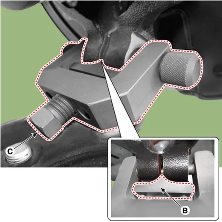
|
| (4)
|
Install the safety wire and main body (A) between the front strut and the lower arm.
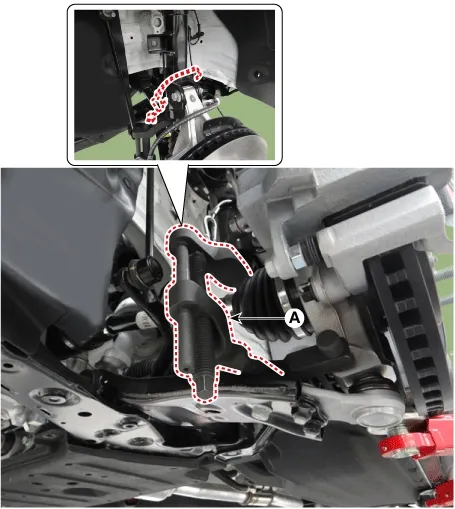
|
| (5)
|
After installing C clamp (A), rotate the handle (B) clockwise until the clamp is fixed on the lower
arm.
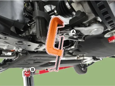
|
| (6)
|
Tighten the main body bolt (A) slowly and remove the lower arm from the front knuckle.
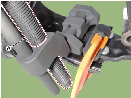
|
|
| 6. |
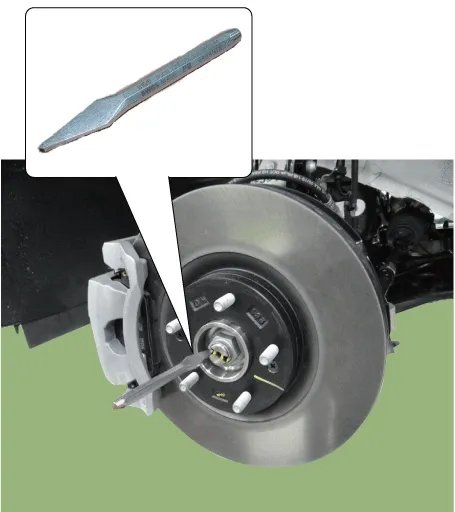
By hammering on a chisel, unlock the driveshaft lock hub nut caulking.
|
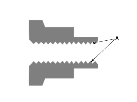
If there is screw thread (A) on the end of the nut, unlock the caulking by using a chisel and then
remove the nut to prevent damaging driveshaft screw thread.
|
|
| 7. |
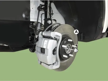
Remove the caulking nut (A) from the front axle.
Tightening torque :
294.2 - 313.8 N·m (30.0 - 32.0 kgf·m, 217.0 - 231.5 lb·ft)
|
|
•
|
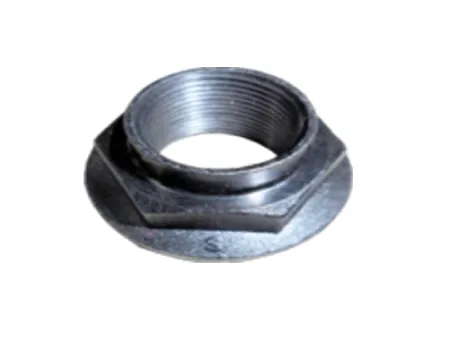
The driveshaft lock nut must be replaced with new one. When replacing the drive lock hub
nut, use only the nut with screw thread (A) on the end.
|
|
•
|
When replacing the drive lock hub nut, use only the nut with screw thread (A) on the end.
|
|
•
|
Tighten the driveshaft lock hub nut to the specified tightening torque, and caulk by using
a chisel and hammer.
|
|
•
|
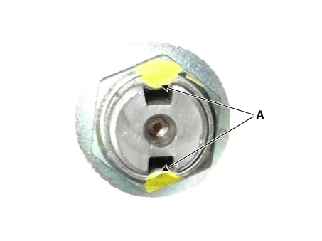
If there are two key seats, perform on all two seats.
Caulking depth (A) : 1.5 mm (0.0591 in)
|
|
|
|
| 8. |
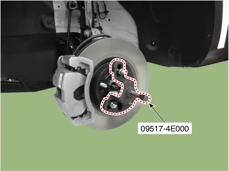
Disconnect the driveshaft from the axle hub by using the SST (09517-4E000).
|
Removing the driveshaft, do not force pull or over deflect the axle.
|
|
| 9. |
Remove the front brake disc.
(Refer to Brake System - "Front Brake Disc")
|
| 10. |
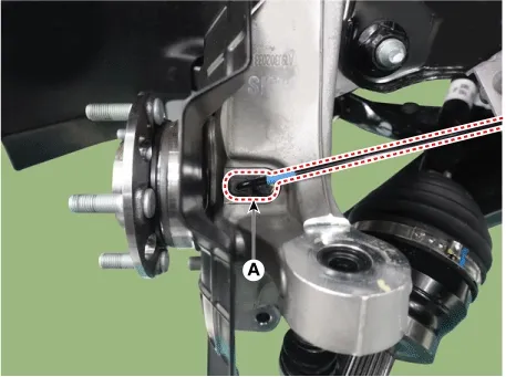
Separate the front wheel speed sensor (A) after removing the bolt.
Tightening torque :
8.8 - 13.7 N·m (0.9 - 1.4 kgf·m, 6.5 - 10.1 lb·ft)
|
|
| 11. |
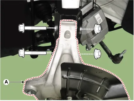
Remove the front axle (A) after removing the front strut bolts and nuts.
Tightening torque :
235.3 - 255.0 N·m (24.0 - 26.0 kgf·m, 173.6 -188.0 lb·ft)
|
|
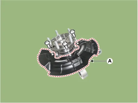
| 1. |
Remove the dust cover (A) from the knuckle.
Tightening torque :
6.9 - 10.8 N·m (0.7 - 1.1 kgf·m, 5.1 - 8.0 lb·ft)
|
|
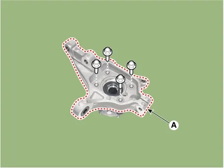
| 2. |
Remove the hub bearing mounting bolts.
Tightening torque :
127.5 - 147.1 N·m (13.0 - 15.0 kgf·m, 94.0 - 108.5 lb·ft)
|
|
| 1. |
Check the hub for cracks and the splines for wear.
|
| 2. |
Check the brake disc for scoring and damage.
|
| 3. |
Check the knuckle for cracks.
|
| 4. |
Check the bearing for cracks or damage.
|
| 1. |
Assemble in the reverse order of disassembly.
|
| 1. |
Install in the reverse order of removal.
|
| 2. |
Check the front alignment.
(Refer to Suspension System - "Alignment")
|
Components
1. Front brake disc2. Dust cover
3. Front hub assembly4. Front knuckle...
Removal
1.
Disconnect the (-) battery terminal.
2.
Remove the front wheel and tire.
(Re...
See also:
Filter replacement
It must be replaced when necessary, and should not be washed.
You can clean the filter when inspecting the air cleaner element. Clean the filter
by using compressed air.
1. Loosen the air clean ...
TJ Joint Installation
1.
Wrap tape around the driveshaft spline(TJ) to prevent damage to
the boot.
2.
Using the alignment marks (D) made during disassembly as a ...
Battery Vehicle parasitic current inspection
1.
Turn the all electric devices OFF, and then turn the ignition
switch OFF.
2.
Close all doors except the engine hood, and then lock all d ...


 Front Axle Assembly Components and Components Location
 Front Hub Assembly Repair procedures
