Kia Sorento: Delivery Pipe Removal and Installation - Fuel Delivery System - Engine Control / Fuel SystemKia Sorento: Delivery Pipe Removal and Installation

Kia Sorento (MQ4, 2021-2026) Service Manual / Engine Control / Fuel System / Fuel Delivery System / Delivery Pipe Removal and Installation

Removal
Low Pressure Delivery Pipe
1.
Release the residual pressure in fuel line.
(Refer to Fuel Delivery System - "Release Residual Pressure in Fuel Line")
2.
Disconnect the battery negative ( - ) terminal.
3.
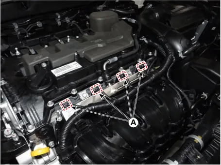
Disconnect the injector connectors (A).

Engine Control / Fuel System — Fuel Delivery System / Delivery Pipe / Removal and Installation / Removal illustration

4.
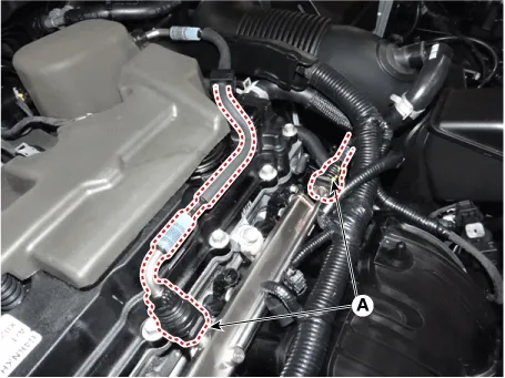
Disconnect the fuel injection quick-connectors (A).

Engine Control / Fuel System — Fuel Delivery System / Delivery Pipe / Removal and Installation / Removal illustration

Note
•
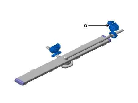
Open the clamp cover (A) before disconnecting the quick connector.

Engine Control / Fuel System — Fuel Delivery System / Delivery Pipe / Removal and Installation / Removal illustration

•
If the clip is damaged, it can cause a fuel leak due to bad connection and could result in a fire.
•
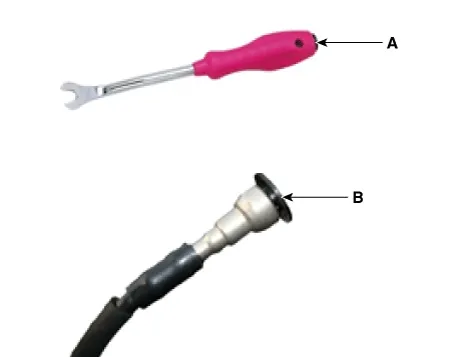
When using the clip removing tool (A), be careful not to damage the plastic clip (B).

Engine Control / Fuel System — Fuel Delivery System / Delivery Pipe / Removal and Installation / Removal illustration

5.
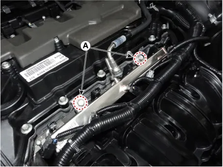
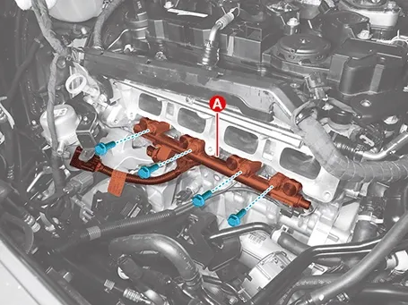
Remove the delivery pipe after removing the mounting bolts (A).

Tightening torque :
18.6 - 23.5 N·m (1.9 - 2.4 kgf·m, 13.7 - 17.4 lb·ft)

Engine Control / Fuel System — Fuel Delivery System / Delivery Pipe / Removal and Installation / Removal illustration

6.
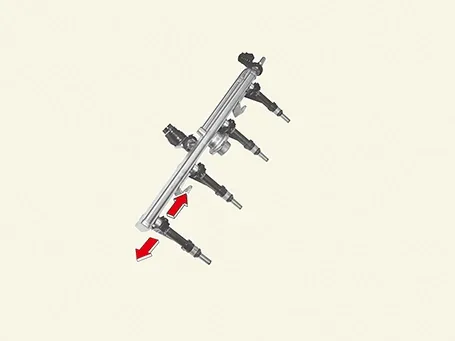
Remove the injector (A) from delivery pipe after releasing the fixing clip to the arrow direction.

Engine Control / Fuel System — Fuel Delivery System / Delivery Pipe / Removal and Installation / Removal illustration

Engine Control / Fuel System — Fuel Delivery System / Delivery Pipe / Removal and Installation / Removal illustration

High Pressure Delivery Pipe
1.
Release the residual pressure in fuel line.
(Refer to the Fuel Delivery System - "Release Residual Pressure in Fuel Line")
2.
Disconnect the battery negative ( - ) terminal.
3.
Remove the air cleaner.
(Refer to Engine Mechanical System - "Air Cleaner")
4.
Remove the high pressure fuel pipe.
(Refer to Fuel Delivery System - "Fuel Line")
5.
Remove the intake manifold.
(Refer to Engine Mechanical System - "Intake Manifold")
6.
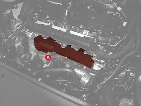
Remove the injector foam (A).

Engine Control / Fuel System — Fuel Delivery System / Delivery Pipe / Removal and Installation / Removal illustration

7.
Remove the delivery pipe & injector assembly (A) after removing the mounting bolts.

Tightening torque :
18.6 - 23.5 N·m (1.9 - 2.4 kgf·m, 13.7 - 17.4 lb·ft)

Engine Control / Fuel System — Fuel Delivery System / Delivery Pipe / Removal and Installation / Removal illustration

8.
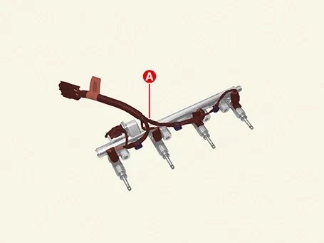
Remove the injector wiring (A) after disconnecting injector & rail pressure sensor connector and releasing the clip.

Engine Control / Fuel System — Fuel Delivery System / Delivery Pipe / Removal and Installation / Removal illustration

9.
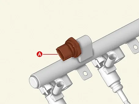
Remove the Rail Pressure Sensor (RPS) (A).

Tightening torque :
29.4 - 34.3 N·m (3.0 - 3.5 kgf·m, 21.7 - 25.3 lb·ft)

Engine Control / Fuel System — Fuel Delivery System / Delivery Pipe / Removal and Installation / Removal illustration

10.
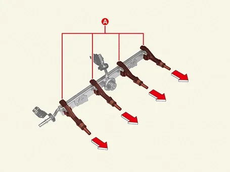
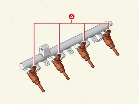
Remove the injector (A) from the delivery pipe.

Engine Control / Fuel System — Fuel Delivery System / Delivery Pipe / Removal and Installation / Removal illustration

Installation
1.
Install in the reverse order of removal.
Note
•
Do not reuse the high pressure fuel pipe.
•
Be careful not to transform the shape of the high pressure fuel pipe.
•
Torque wrench should not be tilt when you tighten the nut.
•
Install the component to the specified torque.
•
Inspect fuel leakage after installing the high pressure fuel pipe assembly.
•
Be careful not to damage the injector tip, when installing injector module assembly.
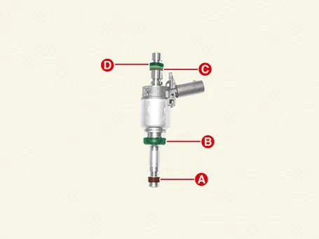
[GDI Injector]
1) When reusing the injector, replace it with a new one.
A : Combustion seal
(Refer to Injector - "Replacement")
B : Rubber washer
(When installing the rubber washer, mount the steel plate faced to the cylinder mount and the rubber plate faced to the injector body.)
C : Support disc
D : O-ring

Engine Control / Fuel System — Fuel Delivery System / Delivery Pipe / Removal and Installation / Installation illustration

2) Apply engine oil to the injector O-ring.
3) Don’t apply engine oil to the combustion seal.
4) When insert the injector, be careful not to damage the injector tip.
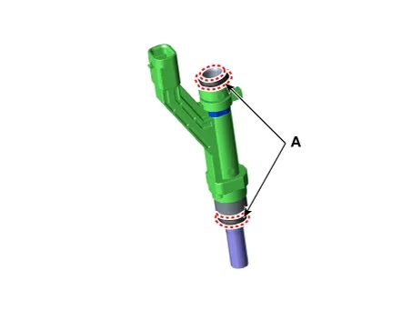
[MPI Injector]
1) Do not reuse injector O-ring (A).

Engine Control / Fuel System — Fuel Delivery System / Delivery Pipe / Removal and Installation / Installation illustration

2) Apply engine oil to the injector O-ring.
2.
Check for leakage the fuel after installation.
Delivery Pipe Components and Components Location

Component Location 1. High Pressure Fuel Pump2. High Pressure Fuel Pipe3. Rail Pressure Sensor (RPS)4. Low Pressure Fuel Injector 5. High Pressure Fu...
Filler-Neck Assembly Components and Components Location
Components 1. Filler-Neck Assembly...
See also:

System settings
Press the key Select [System] Select menu through TUNE knob Memory Information Displays currently used memory and total system memory. Select [Memory Information] OK The currently us ...

Compressor Disassembly and Reassembly
Special Service Tool Tool Name / Number Illustration Description 09977 - 3R000 ...

Description
The Electronic Throttle Control (ETC) System consists of a throttle body with an integrated control motor and throttle position sensor (TPS). Instead of the traditional throttle cable, an Acc ...

Copyright © www.ksmanual.com 2014-2026 - 0.0551