Kia Sorento: Cylinder Head Cover Repair procedures - Cylinder Head Assembly - Engine Mechanical SystemKia Sorento: Cylinder Head Cover Repair procedures

Kia Sorento (MQ4, 2021-2026) Service Manual / Engine Mechanical System / Cylinder Head Assembly / Cylinder Head Cover Repair procedures

Removal
Note
•
Use fender covers to avoid damaging painted surfaces.
•
To avoid damage, unplug the wiring connectors carefully while holding the connector portion.
Information
Mark all wiring and hoses to avoid misconnection.
1.
Release the residual pressure in fuel line.
(Refer to Fuel Delivery System - "Release Residual Pressure in Fuel Line")
2.
Disconnect the battery negative ( - ) terminal.
3.
Remove the engine cover.
(Refer to Engine and Transaxle Assembly - "Engine Cover")
4.
Remove the air intake hose.
(Refer to Intake and Exhaust System - "Air Cleaner")
5.
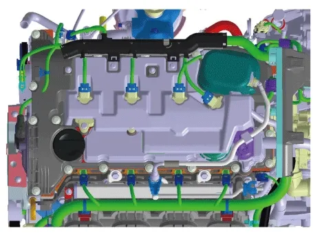
Disconnect the engine wiring connectors and harness clamps around the cylinder head cover.
Then, remove the connector brackets and wiring protector.

Tightening torque :
7.8 - 9.8 N·m (0.8 - 1.0 kgf·m , 5.7 - 7.2 lb·ft)

Engine Mechanical System — Cylinder Head Assembly / Cylinder Head Cover / Repair procedures / Removal illustration

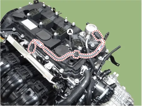
6.
Remove the high pressure fuel hose (A).

Engine Mechanical System — Cylinder Head Assembly / Cylinder Head Cover / Repair procedures / Removal illustration

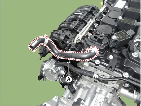
7.
Remove the breather hose (A).

Engine Mechanical System — Cylinder Head Assembly / Cylinder Head Cover / Repair procedures / Removal illustration

8.
Remove the high pressure fuel pipe.
(Refer to Engine Control/Fuel System - "High Pressure Fuel Pump")
9.
Remove the high pressure fuel pump.
(Refer to Engine Control/Fuel System - "High Pressure Fuel Pump")
10.
Remove the ignition coils.
(Refer to Engine Electrical System - "Ignition Coil”)
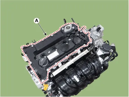
11.
Remove the cylinder head cover (A).

Engine Mechanical System — Cylinder Head Assembly / Cylinder Head Cover / Repair procedures / Removal illustration

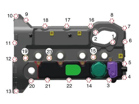
Note
Remove the bolts in the order shown below.

Engine Mechanical System — Cylinder Head Assembly / Cylinder Head Cover / Repair procedures / Removal illustration

Installation
1.
Install the cylinder head cover.
(1)
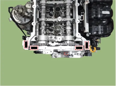
The hardening sealant located on the upper area between timing chain cover and cylinder head should be removed before assembling cylinder head cover.
(2)
Apply a sealant for liquid gasket on the timing chain cover and the area marked on the top of the cylinder head and then assemble these parts within 5 minutes.

Bead width : 4.0 - 5.0 mm (0.15 - 0.19 in.)
Sealant : THREEBOND 1217H / LOCTITE 5900H or equivalent

Engine Mechanical System — Cylinder Head Assembly / Cylinder Head Cover / Repair procedures / Installation illustration

(3)
Install the cylinder head cover (A).

Engine Mechanical System — Cylinder Head Assembly / Cylinder Head Cover / Repair procedures / Installation illustration

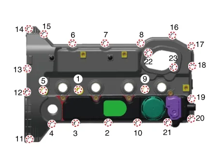
Note
Tighten the whole cylinder head cover bolts to the 1st-step torque in the order shown below,and then tighten to the 2nd-step torque once again.

Tightening torque :
1st step : 3.9 - 5.8 N·m (0.4 - 0.6 kgf·m , 2.8 - 4.3 lb·ft, 34.7 - 52.0 lb·in)
2nd step : 7.8 - 9.8 N·m (0.8 - 1.0 kgf·m , 5.7 - 7.2 lb·ft, 69.4 - 86.7 lb·in)

Engine Mechanical System — Cylinder Head Assembly / Cylinder Head Cover / Repair procedures / Installation illustration

Note
•
Remove the residual oil and cutting oil from the upper surface of the cam carrier before installing the cylinder head cover.
•
Make sure the gasket contact surfaces are clean and dry.
•
Do not fill the engine oil within at least 30 minutes after the installation.
•
Do not reuse cylinder head cover gasket.
•
Do not run the engine or pressurize the inside of the engine within 30 minutes after assembling the cylinder head cover.
2.
Install in the reverse order of removal.
Components and Components Location
Components 1. Camshaft bearing cap2. Exhaust camshaft3. Exhaust CVVT assembly4. Intake camshaft5. Intake E-CVVT assembly6. Cam carrier 7. Cy...
CVVT & Camshaft Description and Operation
Description Continuous Variable Valve Timing (CVVT) system advances or retards the valve timing of the intake and exhaust valve in accordance with the ECM control signal which is calcu...
See also:

Fuel Filler Door Release Actuator Inspection
1. Remove the fuel filler cover (A) after loosening screws (2EA). 2. Remove the fuel filler door module (A). ...

Description and Operation
Description Emissions Control System consists of three major systems. • The Crankcase Emission Control System pre ...

Relay Box (Passenger Compartment) Installation
1. Install IPM(Intelligent intergrated Platform Module). 2. Connect the IPM connector. 3. Install the crash pad ...

Copyright © www.ksmanual.com 2014-2026 - 0.0536