
 Kia Sorento: Cylinder Block Repair procedures
Kia Sorento (MQ4, 2021-2026) Service Manual / Engine Mechanical System / Cylinder Block / Cylinder Block Repair procedures
| Disassembly |
|

|

| 1. |
Remove the engine and transaxle assembly from a vehicle.
(Refer to Engine And Transaxle Assembly - "Engine And Transaxle
Assembly")
|
| 2. |
Remove the automatic transaxle.
(Refer to Automatic Transaxle System - "Automatic
Transaxle")
|
| 3. |
Remove the drive plate.
(Refer to Cylinder Block - "Drive Plate")
|
| 4. |
Remove the rear oil seal.
(Refer to Cylinder Block - "Rear Oil Seal")
|
| 5. |
Install the engine to engine stand for disassembly.
|
| 6. |
Remove the cylinder head cover.
(Refer to Cylinder Head Assembly - "Cylinder Head Cover")
|
| 7. |
Remove the oil pan.
(Refer to Lubrication System - "Oil Pan")
|
| 8. |
Remove the timing chain cover.
(Refer to Timing System - “Timing Chain Cover”)
|
| 9. |
Remove the timing chain.
(Refer to Timing System - “Timing Chain”)
|
| 10. |
Remove the Integrated thermal management module (ITM).
(Refer to Cooling System - "Integrated Thermal Management Module
(ITM)")
|
| 11. |
Remove the intake/exhaust CVVT and camshaft assembly.
(Refer to Cylinder Head Assembly - "CVVT & Camshaft")
|
| 12. |
Remove the intake manifold.
(Refer to Intake And Exhaust System - "Intake Manifold")
|
| 13. |
Remove the exhaust manifold.
(Refer to Intake And Exhaust System - "Exhaust Manifold")
|
| 14. |
Remove the EGR cooler.
(Refer to Intake And Exhaust System - "EGR cooler")
|
| 15. |
Remove the cylinder head.
(Refer to Cylinder Head Assembly - "Cylinder Head")
|
| 16. |
Remove the oil pump.
(Refer to Lubrication System - "Oil Pump")
|
| 17. |
Remove the balance shaft assembly.
(Refer to Lubrication System - "Balance Shaft Assembly")
|
| 18. |
Remove the water pump.
(Refer to Cooling System - "Water Pump")
|
| 19. |
Remove the alternator.
(Refer to Engine Electrical System - "Alternator")
|
| 20. |
Refer to oil filter & oil cooler.
(Refer to Lubrication System - "Oil Filter & Oil
Cooler")
|
| 21. |
Remove the lower crankcase.
(Refer to Cylinder Block - "Crankshaft")
|
| 22. |
Remove the piston and connecting rod assembly.
(Refer to Cylinder Block - "Piston and Connecting Rod")
|
| 23. |
Remove the crankshaft.
(Refer to Cylinder Block - "Crankshaft")
|
| 24. |
Remove the water jacket insert.
(Refer to Cylinder Block - "Water Jacket Insert")
|
| 25. |
Remove the knock sensor.
(Refer to Engine Control/Fuel System - "Knock Sensor
(KS)")
|
| 26. |
Remove the crankshaft position sensor (CKPS).
(Refer to Engine Control/Fuel System - "Crankshaft Position Sensor
(CKPS)")
|
| 27. |
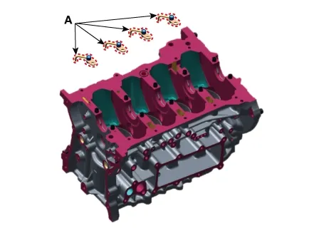
Remove the piston cooling oil jet (A).
|
| Inspection |
| 1. |
Remove the gasket debris on the top of cylinder block using a scraper.
|
| 2. |
Clean the cylinder block thoroughly with a soft brush and solvent.
|
| 3. |
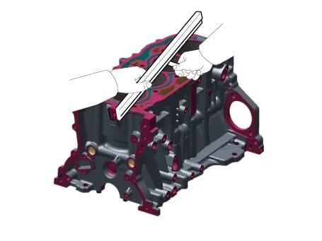
Measure the flatness of the top surface of cylinder block.
Measure the flatness of the surface in contact with the cylinder head gasket using the precise square ruler
and feeler gauge.
|
| 4. |
Visually inspect the inside of cylinder bore for scratches, etc., and replace the cylinder block if
noticeable scratches are found.
|
| 5. |
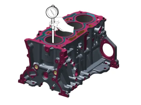
Measure the cylinder bore inner diameter in the axial and axial orthogonal directions using a cylinder bore
gauge.
|
| Reassembly |
|
| 1. |
Install the piston cooling oil jet (A).
|
| 2. |
Install the crankshaft.
(Refer to Cylinder Block - "Crankshaft")
|
| 3. |
Inspect the crankshaft end play.
(Refer to Cylinder Block - "Crankshaft")
|
| 4. |
Remove the lower crankcase and then inspect the oil clearance of crankshaft bearing.
(Refer to Cylinder Block - "Crankshaft")
|
| 5. |
Install the piston and connecting rod assembly.
(Refer to Cylinder Block - "Piston and Connecting Rod")
|
| 6. |
Inspect the oil clearance of connecting rod bearing cap.
(Refer to Cylinder Block - "Piston and Connecting Rod")
|
| 7. |
Inspect the connecting rod end play.
(Refer to Cylinder Block - "Piston and Connecting Rod")
|
| 8. |
Assemble the other parts in the reverse order of disassembly.
|
Disassembly
...
 Crankshaft Repair procedures
 Cylinder Head Assembly
See also:
Door Scuff Trim Repair Procedures
Removal and Installation
Front Door Scuff Trim
1.
Remove the front door body side weather strip.
(Refer to Door (Front) - &q ...
Description and Operation
Description
The system detects the passenger in the vehicle and prevents the driver from getting off the vehicle with the
passenger in the back.
Op ...
USB Charger Circuit Diagram
Circuit Diagram
[Floor Console Tray / Rear Console Cover]
[Front Seat Back Board]
[Lu ...
Manuals list
- Kia Sorento MQ4 2021-2026 Owners Manual
- Kia Sorento XM 2011-2015 Owners Manual
- Kia Sorento XM 2011-2015 Service Manual

Copyright © www.ksmanual.com 2014-2026 - 0.0628