 Kia Sorento: CVVT & Camshaft Repair procedures
CVVT and Camshaft
| 1. |
Remove the timing chain.
(Refer to Timing System - "Timing Chain")
|
| 2. |
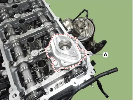
Remove the high pressure fuel pump bracket (A).
|
| 3. |
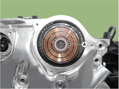
Remove it by breaking the center of E-CVVT motor plug (A).
|
•
|
Remove after 30 minutes of switching "OFF" the ignition to drain out the oil
inside the E-CVVT motor plug.
|
|
•
|
Do not tilt the front of engine (timing chain cover side) downward as residual oil may
flowout during E-CVVT motor plug removal.
|
|
•
|
If oil flows out during E-CVVT motor plug removal, wipe off immediately and block the
motorshaft inlet with a clean towel.
|
|
|
| 4. |
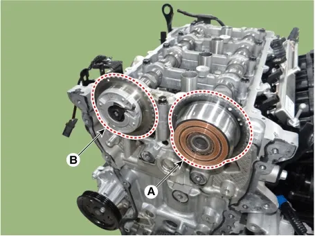
Remove the intake E-CVVT assembly (A) and exhaust CVVT assembly (B).
|
•
|
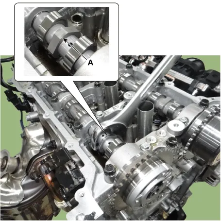
When removing the CVVT assembly bolt, hold the camshaft (A) with a wrench to prevent the
camshaft from rotating.
|
|
|
| 5. |
Remove the camshaft.
| (1)
|
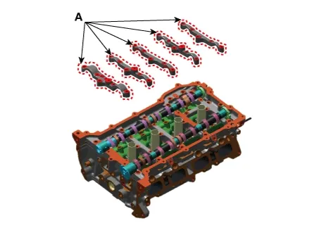
Remove the camshaft bearing caps (A).
|
Be careful not to change the position and direction of the camshaft bearing caps.
|
|
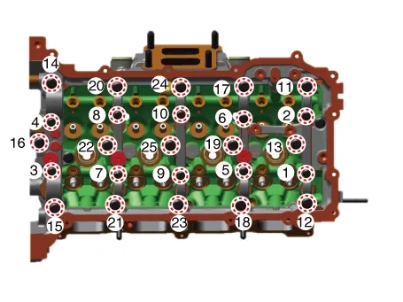
Remove the camshaft bearing caps in the sequence shown below.
|
|
| (2)
|
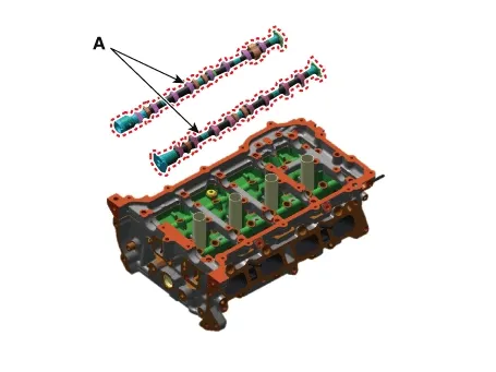
Remove the camshafts (A).
|
|
CVVT amd Camshaft Assembly
| 1. |
Remove the timing chain.
(Refer to Timing System - "Timing Chain")
|
| 2. |
Remove the high pressure fuel pump bracket (A).
|
| 3. |
Remove the intake/exhaust CVVT and camshaft assembly.
| (1)
|
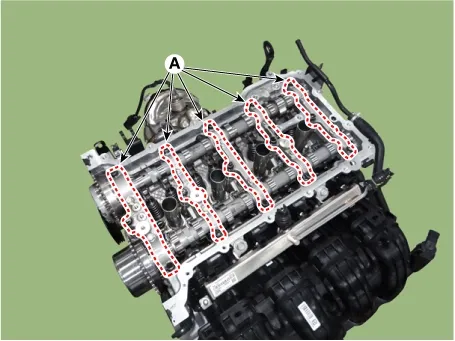
Remove the camshaft bearing caps (A).
|
Be careful not to change the position and direction of camshaft bearing caps.
|
|
Remove the camshaft bearing caps in the sequence shown.
|
|
| (2)
|
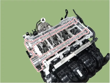
Remove the intake/exhaust CVVT and camshaft assembly (A).
|
|
| 1. |
Inspect the cam lobe height.
Using a micrometer, measure the cam lobe height.
Intake : 39.5mm (1.5551 in.)
Exhaust : 37.6mm (1.4803 in.)
|
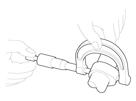
Inspect the cam lobe surface for abnormal wear and damage. Replace if necessary.
|
| 2. |
Inspect the camshaft journal clearance.
| (1)
|
Clean the bearing caps and camshaft journals.
|
| (2)
|
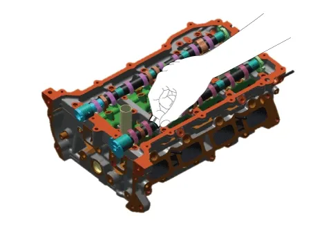
Place the camshafts on the cam carrier.
|
| (3)
|
Lay a strip of plastic gauge across each of the camshaft journal.
|
| (4)
|
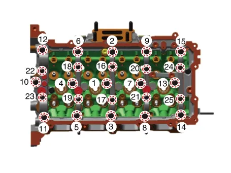
Install the camshaft bearing caps (A) and tighten the bolts to the specified torque.
Tightening torque :
Step 1
M6 : 4.9 - 7.8 N·m (0.5 - 0.8 kgf·m , 3.6 - 5.7 lb·ft, 43.4 - 69.4 lb·in)
M8 : 9.8 - 11.7 N·m (1.0 - 1.2 kgf·m , 7.2 - 8.6 lb·ft)
Step 2
M6 : 11.7 - 13.7 N·m (1.2 - 1.4 kgf·m , 8.6 - 10.1 lb·ft, 104.2 - 121.5 lb·in)
M8 : 18.6 - 22.5 N·m (1.9 - 2.3 kgf·m , 13.7 - 16.6 lb·ft)
|
|
Install the camshaft bearing caps in the sequence shown.
|
|
Do not turn the camshaft.
|
|
| (5)
|
Remove the camshaft bearing caps (A).
|
Be careful not to change the position and direction of camshaft bearing caps.
|
|
Remove the camshaft bearing caps in the sequence shown.
|
|
| (6)
|
Measure the plastic gauge at its widest point.
Camshaft cap oil clearance
[Specified value]
No.1 journal : 0.037 - 0.065 mm (0.00114 - 0.00224 in.)
No.2, 3, 4, 5 journal : 0.037 - 0.067 mm (0.00145 - 0.00263 in.)
|
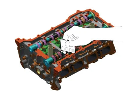
If the oil clearance is greater than maximum value, replace the camshaft. If necessary, replace
cylinder head.
|
| (7)
|
Completely remove the plastic gauge.
|
|
| 3. |
Inspect the camshaft end play.
| (1)
|
Install the camshaft.
|
| (2)
|
Using a dial gauge, measure the end play while moving the camshaft back and forth.
Camshaft end play
[Standard value] : 0.09 - 0.23 mm (0.0035 - 0.0090 in.)
|
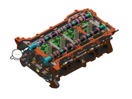
If the end play is greater than maximum value, replace the camshaft. If necessary, replace cylinder
head.
|
|
CVVT and Camshaft Assembly
| 1. |
Install the intake and exhaust CVVT & camshaft assembly.
| (1)
|
Install the intake and exhaust CVVT & camshaft assembly (A).
|
When installing the camshaft, apply engine oil to the cam carrier journal and then apply
engine oil to the camshaft journal after installing the camshaft.
|
|
| (2)
|
Install the camshaft bearing caps (A) and tighten the bolts to the specified torque.
Tightening torque :
Step 1
M6 : 4.9 - 7.8 N·m (0.5 - 0.8 kgf·m , 3.6 - 5.7 lb·ft, 43.4 - 69.4 lb·in)
M8 : 9.8 - 11.7 N·m (1.0 - 1.2 kgf·m , 7.2 - 8.6 lb·ft)
Step 2
M6 : 11.7 - 13.7 N·m (1.2 - 1.4 kgf·m , 8.6 - 10.1 lb·ft, 104.2 - 121.5 lb·in)
M8 : 18.6 - 22.5 N·m (1.9 - 2.3 kgf·m , 13.7 - 16.6 lb·ft)
|
|
Be careful not to change the position and direction of camshaft bearing caps.
|
|
Install the camshaft bearing caps in the sequence below.
|
|
|
| 2. |
Install the high pressure fuel pump bracket (A).
Tightening torque :
18.6 - 23.5 N·m (1.9 - 2.4 kgf·m , 13.7 - 17.3 lb·ft)
|
|
| 3. |
Install the timing chain.
(Refer to Timing System - "Timing Chain")
|
CVVT and Camshaft
| 1. |
Install the camshaft.
| (1)
|
Install the camshafts (A).
|
When installing the camshaft, apply engine oil to the cam carrier journal and then apply
engine oil after installing the camshaft.
|
|
| (2)
|
Install the camshaft bearing caps (A).
Tightening torque :
Step 1
M6 : 4.9 - 7.8 N·m (0.5 - 0.8 kgf·m , 3.6 - 5.7 lb·ft, 43.4 - 69.4 lb·in)
M8 : 9.8 - 11.7 N·m (1.0 - 1.2 kgf·m , 7.2 - 8.6 lb·ft)
Step 2
M6 : 11.7 - 13.7 N·m (1.2 - 1.4 kgf·m , 8.6 - 10.1 lb·ft, 104.2 - 121.5 lb·in)
M8 : 18.6 - 22.5 N·m (1.9 - 2.3 kgf·m , 13.7 - 16.6 lb·ft)
|
|
Be careful not to change the position and direction of the camshaft bearing caps.
|
|
Install the camshaft bearing caps in the sequence shown below.
|
|
|
| 2. |
Install the intake E-CVVT assembly (A) and exhaust CVVT assembly (B).
Tightening torque
Intake E-CVVT Assembly :
73.5 - 83.3 N·m (7.5 - 8.5 kgf·m , 54.2 - 61.4 lb·ft)
Exhaust CVVT Assembly :
22.5 - 26.4 N·m (2.3 - 2.7 kgf·m , 16.6 - 19.5 lb·ft) + 28 - 32°
|
|
When installing the CVVT assembly bolt, hold the camshaft (A) with a wrench to prevent the camshaft
from rotating.
|
|
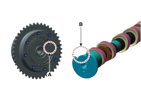
Tighten the bolt when the E-CVVT stopper (A) is matched with the camshaft slot (B).
|
|
| 3. |
Install the high pressure fuel pump bracket (A).
Tightening torque :
18.6 - 23.5 N·m (1.9 - 2.4 kgf·m , 13.7 - 17.3 lb·ft)
|
|
| 4. |
Install the timing chain.
(Refer to Timing System - "Timing Chain")
|
| 5. |
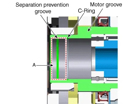
Clean the E-CVVT motor plug mounting surface (A) with oil cleaner.
|
•
|
If the surface is not cleaned, E-CVVT motor plug may be separated due to diminished
separation force from residual oil.
|
|
•
|
When spraying oil cleaner, block around the motor shaft inlet and rotor gap with a clean
towel to prevent inflow of oil from flowing into the rotor gap.
|
|
|
| 6. |
When reusing the E-CVVT cover, inspect the below items.
| (1)
|
If there is sign of leakage from inside the E-CVVT cover, replace it with a new one.
|
| (2)
|
Check the connector brush wear condition.
Specification : More than 5 mm (0.1969 in.)
|
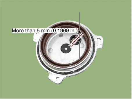
If measurement is below specification, replace the E-CVVT cover with a new one.
|
| (3)
|
Check for damaged oil seal (A) and replace any damaged E-CVVT cover with a new one.
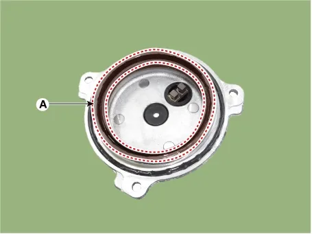
|
| (4)
|
After inspecting E-CVVT, if no problem is found, replace the o-ring (A) with a new one.
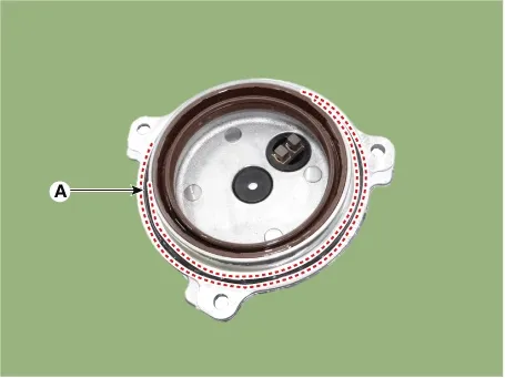
|
|
| 7. |
Install the E-CVVT cover.
| (1)
|
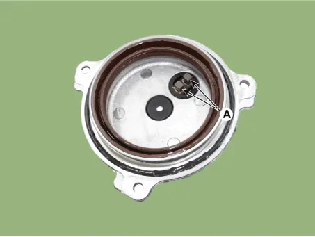
Apply engine oil to the oil seal lip (A).
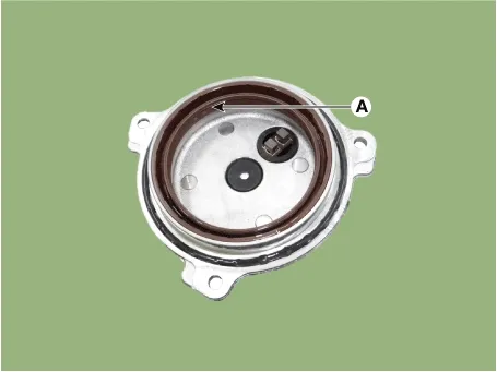
|
When applying oil, keep the connector brush (A) clean from foreign materials.
|
|
| (2)
|
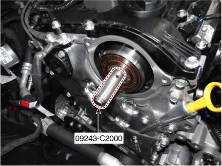
Insert SST(09243 - C2000) into the E-CVVT motor shaft.
|
Correctly mount SST on to the motor shaft.
|
|
| (3)
|
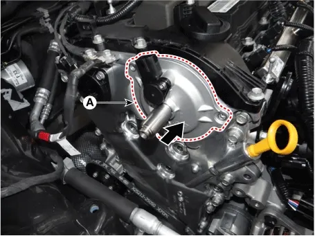
Slowly push the E-CVVT cover (A) until it is flushed with the timing chain cover surface.
|
Installing the E-CVVT cover without SST may cause oil leakage inside the E-CVVT motor due
to damaged or separated E-CVVT oil seal.
|
|
| (4)
|
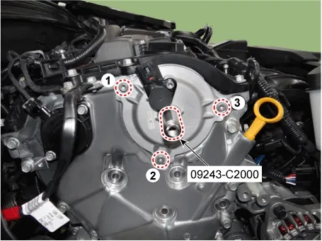
Pre-tighten the bolts in the below sequence, and then remove the SST(09243 - 2C000).
Tightening torque :
0.9 - 1.9 N·m (0.1 - 0.2 kgf·m , 0.7 - 1.4 lb·ft, 8.7 - 17.4 lb·in)
|
|
| (5)
|
Tighten the bolts to the specified torque in the sequence below.
Tightening torque :
9.8 - 11.7 N·m (1.0 - 1.2 kgf·m , 7.2 - 8.6 lb·ft)
|
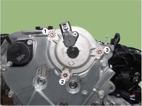
|
|
| 8. |
Install the E-CVVT plug.
| (1)
|
By using SST(09243 - C2000), insert the plug into the E-CVVT cover hole.
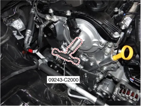
|
| (2)
|
Mount the stopper of SST(09243 - C2000) so that it sits at the end of E-CVVT motor shaft.
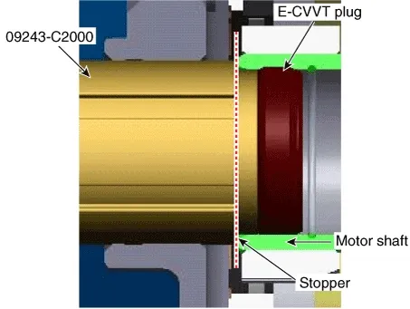
|
|
| 9. |
Inspect the pressed depth of E-CVVT plug.
| (1)
|
By using a steel ruler, measure the distance from E-CVVT cover center boss to the end of motor
shaft (  ).
|
| (2)
|
By using a steel ruler, measure the distance from E-CVVT cover center boss to the end of E-CVVT
plug (  ).
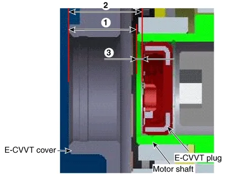
|
| (3)
|
Calculate the pressed depth (  )
of motor plug. If out of specification, reinstall after replacing the E-CVVT plug with a new one.
Specification : 1.1 - 2.1 mm (0.0433 - 0.0826 in.)
|
|
|
| 10. |
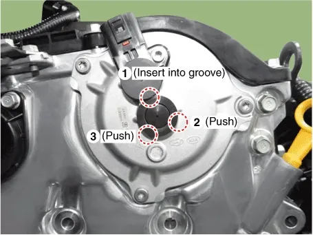
Insert the E-CVVT cover plug so that the protrusion reach to E-CVVT cover groove correctly.
|
•
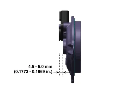
|
Check how much protrude after installing the E-CVVT cover plug.
|
|
•
|
Be careful that the plug is not inserted inside E-CVVT cover beyond the regulated range.
|
|
|
When replacing or reinstalling the electric E-CVVT assembly, make sure to reset the value of
learning using additional function menu of KDS diagnostic.
(Refer to Engine Control/Fuel System - "Electric E-CVVT Motor")additional function menu
of KDS diagnostic.
|
|
Description
Continuous Variable Valve Timing (CVVT) system advances or retards the valve timing of the intake and exhaust valve
in accordance with the ECM control signal which is calcu...



 CVVT & Camshaft Description and Operation
 Cylinder Head Repair procedures
