 Kia Sorento: Battery Inspection
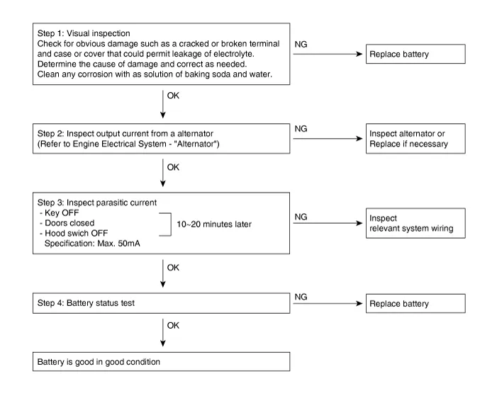
Battery voltage and status
Check the battery voltage and status by using a battery tester.
Battery terminal
| 1. |
Move back and forth to check if the battery terminals are loose or corroded. Clean any corroded terminals.
|
If the battery positive connection is loose, disconnect the ground (GND) cable first before
attempting to remove or tighten the positive connection to prevent personal injury.
|
|
| 2. |
If the battery clamp on battery positive ( + ) terminal is not seated securely:
| (1)
|
Turn ignition switch OFF and disconnect the battery negative ( - ) terminal.
|
| (2)
|
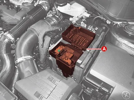
Tighten battery clamp (A) on battery positive ( + ) terminal.
Tightening torque :
7.8 - 9.8 N·m (0.8 - 1.0 kgf·m, 5.8 - 7.2 lb·ft)
|
|
|
| 3. |
If the battery clamp on battery negative ( - ) terminal is not seated securely:
| (1)
|
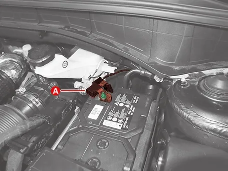
Tighten battery clamp (A) on battery negative ( - ) terminal.
Tightening torque :
7.8 - 9.8 N·m (0.8 - 1.0 kgf·m, 5.8 - 7.2 lb·ft)
|
|
|
Battery condition
Check the battery for damage or deformation. If severe damage, deformation or leakage is found, replace the
battery.
Vehicle parasitic current inspection
[Using the Ammeter]
| 1. |
Turn the all electric devices OFF, and then turn the ignition switch OFF.
|
| 2. |
Close all doors except the engine hood, and then lock all doors.
| (1)
|
Disconnect the hood switch connector.
|
| (3)
|
Close the doors or remove the door switches.
|
|
| 3. |
Wait a few minutes until the vehicle’s electrical systems go to sleep mode.
|
For an accurate measurement of a vehicle parasitic current, all electrical systems should go to
sleep mode. (It takes at least one hour or at most one day.) However, an approximate vehicle parasitic
current can be measured after 10~20 minutes.
|
|
| 4. |
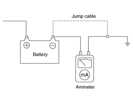
Connect an ammeter in series between the battery ( - ) terminal and the ground cable, and then disconnect
the clamp from the battery ( - ) terminal slowly.
|
•
|
Be careful that the lead wires of an ammeter do not come off from the battery ( - )
terminal and the ground cable to prevent the battery from being reset. In case the battery is
reset, connect the battery cable again, and then start the engine or turn the ignition switch
ON for more than 10 sec. Repeat the procedure from No. 1.
To prevent the battery from being reset during the inspection,
|
| 1) |
Connect a jump cable between the battery ( - ) terminal and the ground cable.
|
| 2) |
Disconnect the ground cable from the battery ( - ) terminal.
|
| 3) |
Connect an ammeter between the battery ( - ) terminal and the ground cable.
|
| 4) |
After disconnecting the jump cable, read the current value of the ammeter.
|
|
|
| 5. |
Read the current value of the ammeter.
|
•
|
If the parasitic current is over the limit value, search for abnormal circuit by removing a fuse
one by one and checking the parasitic current.
|
|
•
|
Reconnect the suspected parasitic current draw circuit fuse only and search for suspected unit by
removing the component connected with the circuit one by one until the parasitic draw drops below
limit value.
|
Limit value (mA) : Below 50 (after 10 - 20 min.)
|
|
| 6. |
Turn the all electric devices OFF, and then turn the ignition switch OFF.
|
| 7. |
Close all doors except the engine hood, and then lock all doors.
| (1)
|
Disconnect the hood switch connector.
|
| (3)
|
Close the doors or remove the door switches.
|
|
| 8. |
Wait a few minutes until the vehicle’s electrical systems go to sleep mode.
|
For an accurate measurement of a vehicle parasitic current, all electrical systems should go to
sleep mode. (It takes at least one hour or at most one day.) However, an approximate vehicle parasitic
current can be measured after 10 - 20 minutes.
|
|
| 9. |
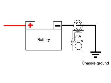
Install the clamp type ammeter on battery negative ( - ) terminal.
|
| 10. |
Read the current value of the ammeter.
|
•
|
If the parasitic current is over the limit value, search for abnormal circuit by removing a fuse
one by one and checking the parasitic current.
|
|
•
|
Reconnect the suspected parasitic current draw circuit fuse only and search for suspected unit by
removing the component connected with the circuit one by one until the parasitic draw drops below
limit value.
|
Limit value (mA) : Below 50 (after 10 - 20 min.)
|
|
AGM Battery Charging
|
Follow the charging method(DIN 41772) defined by German Standards Association (DIN)
|
–
|
I(Constant current) : It is also called the constant current
method. this method is charging by maintaining regularly the current from start the charging to
complete.
|
|
–
|
U(Constant voltage) : It is also called the constant voltage
method. this method is charging by maintaining regularly the voltage from start the charging to
complete.
|
|
–
|
W(Taper current) : It is called also the single current
method. this method is a type of constant current method, and is charging by decreasing the current in
charging step by step.
|
|
| 1. |
Check the state of charge of the battery, and charge the battery if required.
How to charge IU or WU
IU or WU charging voltage (V) : 14.7 [20 - 30°C (68 - 86°F)]
Approximately 24 hours
Minimum charging voltage (V) : 14.4 [20°C (68°F)]
Maximum charging voltage (V) : 14.8 [20°C (68°F)]
A capacity of 10% of the charging current is recommended (e.g. 80 Ah : 100% = 8.0 A of charging
current)
|
|
|
•
|
Do not charge over the 15.2 V, and not quick charge.
|
|
•
|
Do not open or remove the cap on the top of the AGM battery.
|
|
•
|
Since explosive gas is formed in each cell when charging the battery, any actions that may cause
ignition such as fire, sparks, light rays, smoking, etc. during or immediately after charging the
battery are prohibited.
|
|
•
|
Do not open the circuit while the battery is charging as it will generate the spark, keep away from
nearby flammable material.
|
|
|
•
|
The temperature of the battery shall be maintained at approximately 20 - 30°C (68 - 86°F) during
the charging.
|
|
•
|
If the battery sensor is charged while connected to the battery, the sensor may not accurately
detect the state of the battery. Therefore, when the battery is fully charged, use it after about 10
hours (stabilizing time of the battery) at room temperature. Otherwise, it will result in a fault code
or the Alternator Management System (AMS) function may not work.
|
|
Removal and Installation
Air cleaner filter replacement
1.
Lifting the lever (A) to open the air cleaner filter cover (B).
...
Replacement and Air Bleeding
[THETA-Ⅲ 2.5 GDI]
...
See also:
Adjustment
Adjustment
Glass Adjustment
...
Side Airbag (SAB) Module Removal
The side airbag cannot be disassembled from the seat back assembly,
so replace assembly when replacing the side airbag.
...
Front Body C
* These dimensions indicated in this figure are actual-measurement
dimensions. [ Unit : mm (inch) ]
...



 Air Cleaner Filter Replacement
 Cooling System Replacement
