Kia Sorento: Alternator Disassembly and Reassembly - Charging System - Engine Electrical SystemKia Sorento: Alternator Disassembly and Reassembly

Kia Sorento (MQ4, 2021-2026) Service Manual / Engine Electrical System / Charging System / Alternator Disassembly and Reassembly

Special Service Tools
Tool Name / Number
Illustration
Description
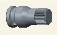
Alternator pulley remover wrench
09373 - 27000

Engine Electrical System — Charging System / Alternator / Disassembly and Reassembly / Special Service Tools illustration

Used for removing / installing alternator pulley

Disassembly
1.
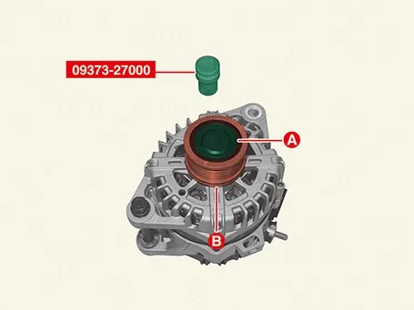
Remove the pulley (B) using the SST (09373 - 27000) after removing the OAD cap (A).

Tightening torque :
75.5 - 81.4 N·m (7.7 - 8.3 kgf·m, 55.7 - 60.0 lb·ft)

Engine Electrical System — Charging System / Alternator / Disassembly and Reassembly / Disassembly illustration

2.
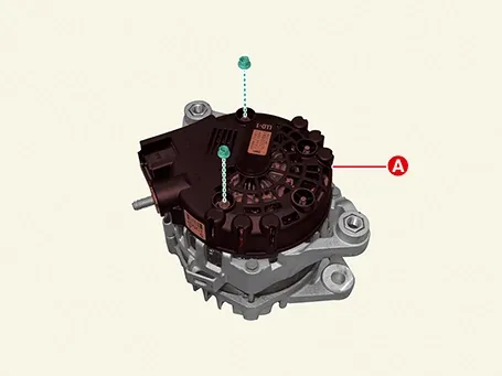
Remove the alternator cover (A) after removing the mounting nuts.

Tightening torque :
3.0 - 4.4 N·m (0.31 - 0.45 kgf·m, 2.2 - 3.3 lb·ft, 26.9 - 39.1 lb·in)

Engine Electrical System — Charging System / Alternator / Disassembly and Reassembly / Disassembly illustration

3.
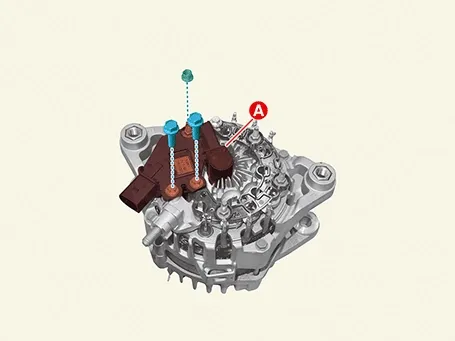
Remove the brush & regulator assembly (A) after removing the mounting bolts and nut.

Tightening torque :
4.0 - 4.4 N·m (0.41 - 0.45 kgf·m, 3.0 - 3.3 lb·ft, 36.0 - 39.1 lb·in)

Engine Electrical System — Charging System / Alternator / Disassembly and Reassembly / Disassembly illustration

4.
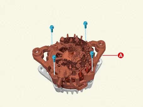
Remove the rectifier assembly (A) after removing the mounting bolts.

Tightening torque :
4.5 - 5.5 N·m (0.46 - 0.56 kgf·m, 3.3 - 4.1 lb·ft, 39.9 - 48.6 lb·in)

Engine Electrical System — Charging System / Alternator / Disassembly and Reassembly / Disassembly illustration

5.
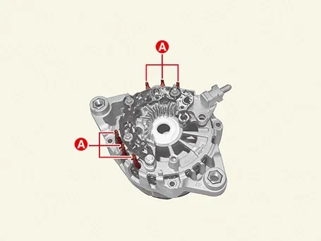
Dissolve the stator lead (A).

Engine Electrical System — Charging System / Alternator / Disassembly and Reassembly / Disassembly illustration

6.
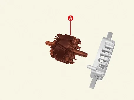
Remove the rotor (A) from the front housing complete.

Engine Electrical System — Charging System / Alternator / Disassembly and Reassembly / Disassembly illustration

Reassembly
1.
Install in the reverse order of disassembly.
Note
•
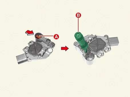
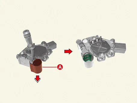
Hold the brush (A) after pushing it in the arrow direction and inserting the pin (B).

Engine Electrical System — Charging System / Alternator / Disassembly and Reassembly / Reassembly illustration

•
Hold the brush while pushing the cap (A) down in the arrow direction.

Engine Electrical System — Charging System / Alternator / Disassembly and Reassembly / Reassembly illustration

•
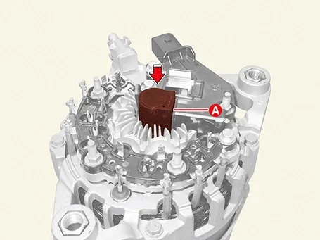
Install the cap (A) by pushing in the arrow direction after installing the brush & regulator assembly.

Engine Electrical System — Charging System / Alternator / Disassembly and Reassembly / Reassembly illustration

•
The OAD must be replaced with the OAD cap.
Alternator Removal and Installation

Removal 1. Disconnect the battery negative ( - ) terminal. 2. Remove the drive belt. (...
Alternator Inspection
Inspection Inspect Rotor 1. Check that there is continuity between the slip rings (C). 2. ...
See also:

CVVT (Continuously Variable Valve Timing) System Description
Continuous Variable Valve Timing (CVVT) system advances or retards the valve timing of the intake and exhaust valve in accordance with the ECM control signal which is calculated by the engine ...

Inspection
[Evap Leak Test] Engine Control Module (ECM) controls Purge Control Solenoid Valve (PCSV) and Canister Close Valve (CCV) for EVAP System diagnosis if the conditions are satisfied ...

Components Location
Supplemental Restraint System Control Module (SRSCM) Driver Airbag (DAB) / Passenger Airbag (PAB) Side Airbag (SAB) Curtain Airbag (CA ...

Copyright © www.ksmanual.com 2014-2026 - 0.0576