 Kia Sorento: Alternator Disassembly
Second Generation XM (2011-2026) / Kia Sorento XM 2011-2026 Service Manual / Engine Electrical System / Charging System / Alternator Disassembly
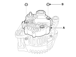
| 1. |
Remove the alternator cover (A) using a screw driver after loosening
the nuts (B).
|
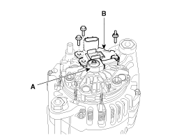
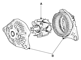
| 2. |
Remove the slip ring guide (A) and then loosen the mounting bolts
and disconnect the brush holder assembly (B).
|
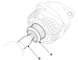
| 3. |
Remove the pulley (A) using the SST (09373-27000) (B).
|
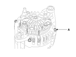
| 4. |
Loosen the 4 through bolts (A).
|
| 5. |
Disconnect the rotor (A) and cover (B).
|
| 6. |
Reassembly is the reverse order of disassembly.
|
 Alternator Installation
1.
Install in the reverse order of removal.
2.
Adjust the alternator belt tension after installation.
(Refer to Engine Mechanical ...
 Alternator Reassembly
1.
Reassemble in the reverse order of disassembly.
ŌĆó
...
See also:
Door Mood Lamp Removal
1.
Disconnect the negative battery terminal.
2.
Remove the front door trim.
(Refer to Body - "Front door")
...
Blower Motor Replacement
1.
Disconnect the negative (-) battery terminal.
2.
Remove the passenger side crash pad under cover (A).
3.
...
SS-B Solenoid Valve(ON/OFF)
SS-B solenoid valve is attached to the valve body and is an on/off solenoid
valve that is used to change gears.
SS-B Solenoid valve(ON/OFF) is installed at valve body.
...
Categories
- Home
- First Generation
- Second Generation
- Kia Sorento XM 2011-2026 Owners Manual
- Kia Sorento XM 2011-2026 Service Manual

Copyright ® www.ksmanual.com 2014-2026