 Kia Sorento: Adjustment
Rear
Turn the cam bolt (A) attached to the rear assist arm clockwise or counterclockwise to adjust the toe. Adjust the
left and right cam bolts to the same amount.
Total : 0.2 ± 0.2 °
Individual : 0.1 ± 0.1 °
|
Cam nut
|
Rotation
|
Increae / Decrease
|
Change (°)
|
RH
|
Clockwise
|
Toe in
|
Toe about 0.44
Camber about 0.06
*Per scale
|
LH
|
Clockwise
|
Toe out
|
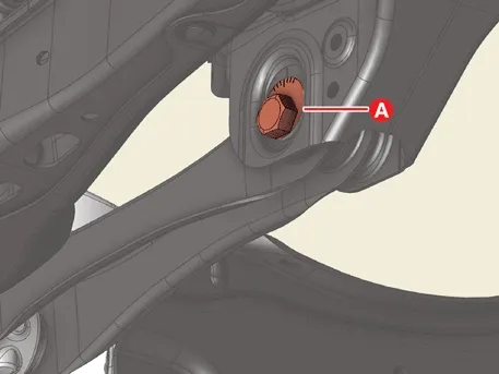
|
The left bolt is a left-handed thread, so be careful to prevent damage to the bolt when tightening and
loosening.
|
•
|
Tightening : counterclockwise
|
|
|
Adjust the toe using total toe.
|
Turn the cam nuts (A) attached to the rear lower arm clockwise or counterclockwise to adjust the camber.
Camber Angle : -1.0 ± 0.5 °
|
Cam nut
|
Rotation
|
Increae / Decrease
|
Change (°)
|
RH
|
Clockwise
|
- Camber
|
Toe about 0.24
Camber about 0.19
*Per scale
|
LH
|
Clockwise
|
+ Camber
|
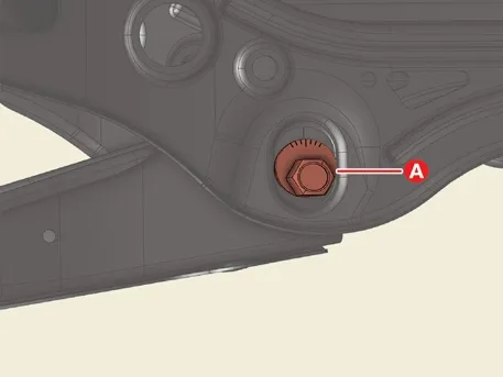
|
The left bolt is a left-handed thread, so be careful to prevent damage to the bolt when tightening and
loosening.
|
•
|
Tightening : counterclockwise
|
|
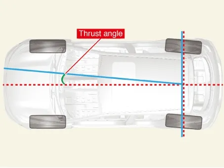
[Front]
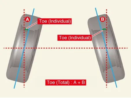
Toe is adjusted by rotation of the tie rod rotation buckle. Turning the tie rod to the rear of the vehicle will
reduce the toe on the front wheels. The adjustment toe is adjusted by turning the left and right tie rods to the same
value.
Total : 0.1 ± 0.2 °
Individual : 0.05 ± 0.1 °
|
| 1. |
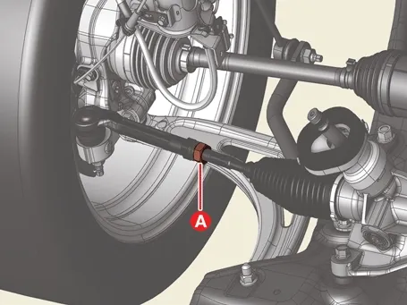
Loosen the tie rod end nut (A) until the toe can be adjusted.
Tightening torque :
49.0 - 53.9 N·m (5.0 - 5.5 kgf·m, 36.2 - 39.8 lb·ft)
|
|
| 2. |
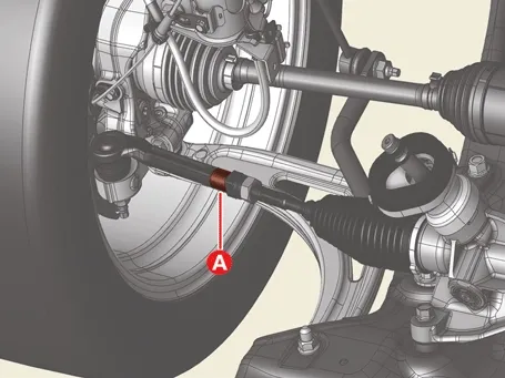
Fix the tie rod end (A) using a wrench to prevent the tie rod from turning when adjusting alignment.
|
| 3. |
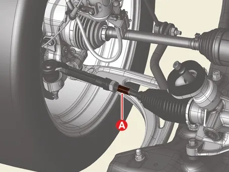
Adjust the toe in the specified value by turning the tie rod turn buckle (A).
|
After toe adjustment, match the remaining number of threads on the left and right equally.
|
|
| 4. |
After adjustment, tighten the tie rod end nut (A) to specification torque.
Tightening torque :
49.0 - 53.9 N·m (5.0 - 5.5 kgf·m, 36.2 - 39.8 lb·ft)
|
|
|
•
|
Be careful not to twist the bellows boot when adjusting the toe.
|
|
•
|
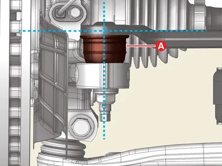
After toe adjustment, adjust the tie rod end position horizontally to ensure that the ball joint
boot (A) is not pressed.
|
|
The camber cannot be adjusted. If the measured camber exceeds the standard limit, repair or replace the relevant
parts and inspect the wheel alignment again.
Camber Angle : -0.5 ± 0.5 °
|
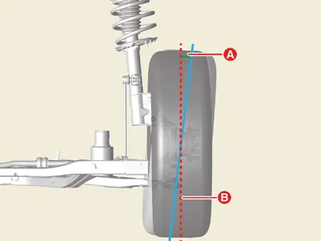
Item
|
Description
|
A
|
Camber Angle
|
B
|
Center line
|
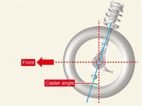
The caster cannot be adjusted. If the measured caster exceeds the standard limit, repair or replace the relevant
parts and inspect the wheel alignment again.
Caster Angle :
2WD : 4.23 ± 0.5 °
4WD : 4.14 ± 0.5 °
|
|
•
|
Before measuring the front wheel alignment, wear, loose and damaged parts of the front suspension
assembly should be replaced.
|
|
•
|
Camber and caster are assembled at the specified value during production and need not be adjusted.
|
|
•
|
If the camber and caster are not within the specified limits, replace the bent or damaged parts.
|
|
•
|
The difference between the left and right wheels of Camber and Caster shall be within 0° ± 0.5°.
|
|
The king pin angle cannot be adjusted. If the measured caster exceeds the standard limit, repair or replace the
relevant parts and inspect the wheel alignment again.
Kingpin Angle :
2WD : 13.8 ± 0.5 °
4WD : 13.6 ± 0.5 °
|
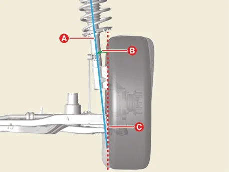
Item
|
Description
|
A
|
Steering Center Line
|
B
|
Kingpin
|
C
|
Center line
|
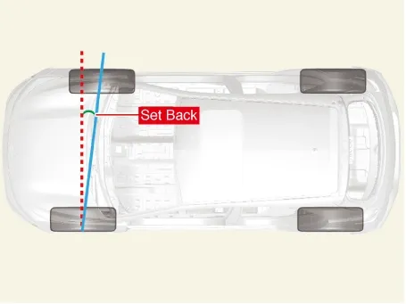
Setback cannot be adjusted, but the value is useful for diagnosing central steering problems, such as tilting.
After repairing a vehicle with a damaged frame, the set-back must be checked. The ideal setback value should be zero.
Wheel Alignment Repair Procedures
1.
When using the wheel alignment tester to check the wheel alignment, align the lift's vehicles
horiz...



 Repair Procedures
 Front Suspension System
