 Kia Sorento: Valve Clearance Inspection And Adjustment
|
Inspect and adjust the valve clearance when the engine is cold (Engine
coolant temperature : 20┬░C (68┬░F)) and cylinder head is installed on
the cylinder block.
|
|
In case of removing the high pressure fuel pump, high pressure fuel
pipe, delivery pipe, and injector, there may be injury caused by leakage
of the high pressure fuel. So donŌĆÖt do any repair work right after engine
stops.
|
|
1. |
Remove the cylinder head cover.
(Refer to Cylinder Head Assembly - "Cylinder Head Cover")
|
|
2. |
Set No.1 cylinder to TDC/compression.
|
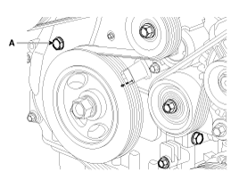
(1) |
Turn the crankshaft pulley and align its groove with the timing
mark "T" of the lower timing chain cover.
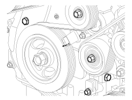
|
|
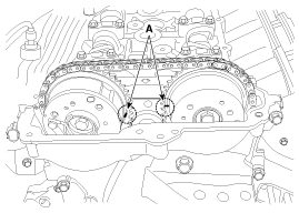
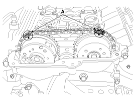
(2) |
Check that the TDC marks (A) of the CVVT sprockets are in straight
line on the cylinder head surface as shown in the illustration.
If not, turn the crankshaft one revolution (360┬░)
|
|
|
3. |
Inspect the valve clearance.
|
(1) |
Check only the valve indicated as shown. Measure the valve clearance.
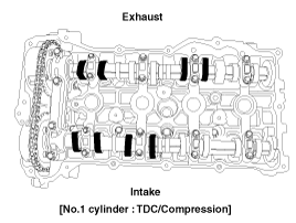
| A. |
Using a thickness gauge, measure the clearance between
the tappet and the base circle of camshaft.
|
| B. |
Record the out-of-specification valve clearance measurements.
They will be used later to determine the required replacement
adjusting tappet.
|
Valve clearance (Engine
coolant temperature : 20┬░C [68┬░F])
[Specification]
Intake : 0.17 ~ 0.23mm (0.0067 ~ 0.0090in.)
Exhaust : 0.27 ~ 0.33mm (0.0106 ~ 0.0129in.)
|
|
|
(2) |
Turn the crankshaft pulley one revolution (360┬░) and align the
groove with timing mark "T" of the lower timing chain cover.
|
|
(3) |
Check only valves indicated as shown. Measure the valve clearance.
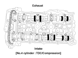
|
|
|
4. |
Adjust the intake and exhaust valve clearance.
|
(1) |
Set the No.1 cylinder to the TDC/compression.
|
|
(2) |
Mark the timing chains (A) on the timing marks of the CVVT sprockets.
|
|
(3) |
Remove the front camshaft bearing cap.
|
|
(4) |
Turn the crankshaft pulley 15┬░ clockwise.
|
|
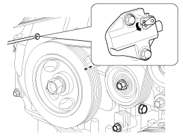
(5) |
Remove the service hole bolt(A) of the timing chain cover.
|
The bolt must not be reused once it has been assembled.
|
|
|
(6) |
Release the ratchet of the timing chain tensioner by pulling
the link down using a thin rod.
|
|
(7) |
Remove the exhaust camshaft bearing cap and exhaust camshaft.
|
|
(8) |
Remove the intake camshaft bearing cap and intake camshaft.
|
When disconnect the timing chain from the CVVT sprocket,
hold the timing chain.
|
|
|
(9) |
Tie down timing chain so that it doesn't move.
|
Be careful not to drop anything inside timing chain
cover.
|
|
|
(10) |
Measure the thickness of the removed tappet using a micrometer.
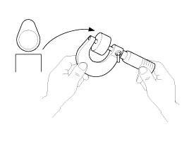
|
|
(11) |
Calculate the thickness of a new tappet so that the valve clearance
comes within the specified value.
Valve clearance [Engine
coolant temperature : 20┬░C(68┬░F)]
T : Thickness of removed tappet
A : Measured valve clearance
N : Thickness of new tappet
Intake : N = T + [A - 0.20 mm (0.0079 in.)]
Exhaust : N = T + [A - 0.30 mm (0.0118 in.)]
|
|
|
(12) |
Select a new tappet with a thickness as close as possible to
the calculated value.
|
Shims are available in 47 size increments of 0.015 mm
(0.0006 in.) from 3.00 mm (0.11 in.) to 3.690 mm (0.1452
in.)
|
|
|
(13) |
Place a new tappet on the cylinder head.
|
|
(14) |
Hold the timing chain, and install the intake camshaft and CVVT
assembly.
|
|
(15) |
Align the timing marks (A) on the timing chains and CVVT sprockets.
|
|
(16) |
Install the exhaust camshaft and CVVT assembly after releasing
the ratchet of the timing chain tensioner.
|
|
(17) |
Install the front bearing cap.
|
|
(18) |
Install the service hole bolt.
Tightening torque :
11.8 ~ 14.7 N.m (1.2 ~ 1.5 kgf.m, 8.7 ~ 10.8 lb-ft)
|
|
|
(19) |
Turn the crankshaft two turns in the operating direction(clockwise),
and then check that the TDC marks (A) of the CVVT sprockets
are in straight line on the cylinder head surface.
|
|
(20) |
Recheck the valve clearance.
Valve clearance [Engine
coolant temperature : 20┬░C(68┬░F)]
[Specification]
Intake : 0.17 ~ 0.23 mm (0.0067 ~ 0.0090 in.)
Exhaust : 0.27 ~ 0.33 mm (0.0106 ~ 0.0129 in.)
|
|
|
1. Camshaft bearing cap
2. Camshaft front bearing cap
3. Exhaust camshaft
4. Intake camshaft
5. Exhaust CVVT assembly
6. Intake CVVT assembly
7. Exhaust camshaft upper ...
1. Cylinder head cover
2. Gasket
...
See also:
Photo Sensor Description
The photo sensor is located at the center of the defrost nozzles.
The photo sensor contains a photovoltaic (sensitive to sunlight) diode.
The solar radiation received by its light receiving ...
Storage compartments
These compartments can be used to store small items.
CAUTION
To avoid possible theft, do not leave valuables in the storage compartment.
Always keep the storage compartment covers closed while ...
Engine Room Under Cover Removal and Installation
1.
Unfasten the fasteners and bolts and then remove the engine room under
cover (A).
Tightening torque:
7.8 ~ 11.7 N.m (0.8 ~ 1.2 kgf ...


 Components
 Cylinder Head Cover Components