 Kia Sorento: Parking brake
Applying the parking brake
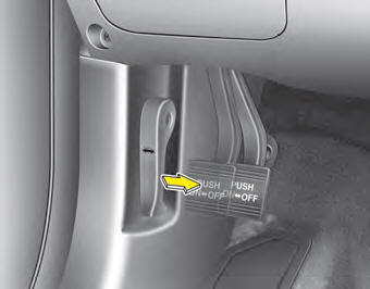
Foot type
To engage the parking brake, first apply the foot brake and then depress the parking brake pedal down as far as possible.
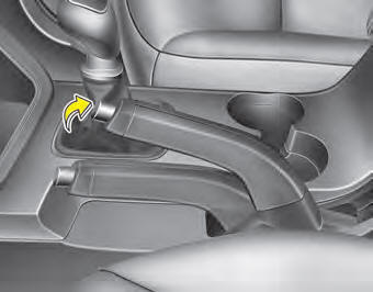
Hand type
To engage the parking brake, first apply the foot brake and then without pressing the release button in, pull the parking brake lever up as far as possible.
In addition it is recommended that when parking the vehicle on a gradient, the shift lever should be positioned in the appropriate low gear on manual transaxle vehicles.
CAUTION
Driving with the parking brake applied will cause excessive brake pad and brake rotor wear.
Releasing the parking brake
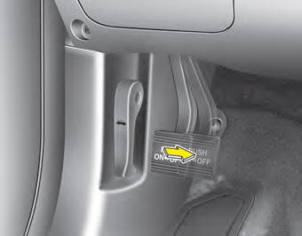
Foot type
To release the parking brake, depress the parking brake pedal a second time while applying the foot brake. The pedal will automatically extend to the fully released position.
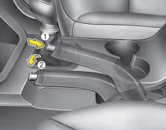
Hand type
To release the parking brake, first apply the foot brake and pull up the parking brake lever slightly. Secondly press the release button (1) and lower the parking brake lever (2) while holding the button.
WARNING
- To prevent unintentional movement when stopped and leaving the vehicle, do not use the shift lever instead of the parking brake. Set the parking brake AND make sure the shift lever is securely positioned in 1st (First) gear or R (Reverse) for manual transaxle equipped vehicles and in P (Park) for automatic transaxle equipped vehicles.
- Never allow anyone who is unfamiliar with the vehicle to touch the parking brake. If the parking brake is released unintentionally, serious injury may occur.
- All vehicles should always have the parking brake fully engaged when parking to avoid inadvertent movement of the vehicle which can injure occupants or pedestrians.
Check the brake warning light by turning the ignition switch ON (do not start the engine). This light will be illuminated when the parking brake is applied with the ignition switch in the START or ON position.
Before driving, be sure the parking brake is fully released and the brake warning light is off.
If the brake warning light remains on after the parking brake is released while the engine is running, there may be a malfunction in the brake system. Immediate attention is necessary.
If at all possible, cease driving the vehicle immediately. If that is not possible, use extreme caution while operating the vehicle and only continue to drive the vehicle until you can reach a safe location or repair shop.
 Power brakes
Your vehicle has power-assisted brakes that adjust automatically through normal
usage.
In the event that the power-assisted brakes lose power because of a stalled engine
or some other reason, you c ...
 Anti-lock brake system (ABS)
WARNING
ABS (or ESC) will not prevent accidents due to improper or dangerous driving
maneuvers. Even though vehicle control is improved during emergency braking, always
maintain a safe distance bet ...
See also:
Special Service Tools
Tool (Number and Name)
IIIustration
Use
09561-11001
Steering wheel puller
Remove the steering wheel
...
Cruise Control
The cruise control system is engaged by the cruise "ON/OFF" main switch
located on right of steering wheel column. The system has the capability to
cruise, coast, accelerate and res ...
SS-B Solenoid Valve(ON/OFF)
SS-B solenoid valve is attached to the valve body and is an on/off solenoid
valve that is used to change gears.
SS-B Solenoid valve(ON/OFF) is installed at valve body.
...
Categories
- Home
- First Generation
- Second Generation
- Kia Sorento XM 2011-2025 Owners Manual
- Kia Sorento XM 2011-2025 Service Manual
