 Kia Sorento: Roof Trim Replacement
Second Generation XM (2011-2025) / Kia Sorento XM 2011-2025 Service Manual / Body (Interior and Exterior) / Exterior / Roof Trim Replacement
Sunvisor Replacement
| 1. |
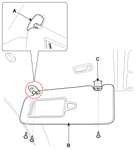
Remove the sunvisor cover (A).
|
| 2. |
After loosening the mounting screws, then remove the sunvisor
(B) and retainer (C).
|
| 3. |
Install in the reverse order of removal.
|
Assist Handle Replacement
| 1. |
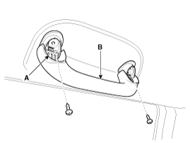
Remove the covers (A), and remove the screws, then remove the
assist handle (B).
|
| 2. |
Install in the reverse order of removal.
|
Overhead Console Lamp Replacement
| 1. |
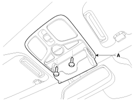
After loosening the mounting screws, then remove the overhead
console lamp assembly (A).
|
| 2. |
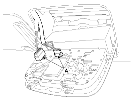
Disconnect the connectors (A).
|
| 3. |
Install in the reverse order of removal.
|
Room Lamp Replacement
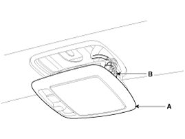
| 1. |
Using a screwdriver or remover, remove the room lamp (A).
|
| 2. |
Disconnect the connector (B).
|
| 3. |
Install in the reverse order of removal.
|
Luggage Room Lamp Replacement
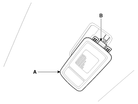
| 1. |
Using a screwdriver or remover, remove the luggage room lamp (A).
|
| 2. |
Disconnect the connector (B).
|
| 3. |
Install in the reverse order of removal.
|
Vanity Lamp Replacement
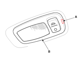
| 1. |
Using a screwdriver (-), push the hook (A), remove the vanity
lamp (B).
|
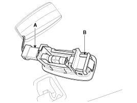
| 2. |
Disconnect the connector (A), remove the vanity lamp (B).
|
| 3. |
Install in the reverse order of removal.
|
Roof Trim Assembly Replacement
|
| 1. |
Remove the following parts.
|
| 2. |
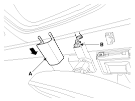
Remove the ECM mirror cover (A).
|
| 3. |
Disconnect the ECM mirror connector (B).
|
| 4. |
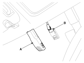
Remove the auto defog sensor cover (A).
|
| 5. |
Disconnect the auto defog sensor connector (B).
|
| 6. |
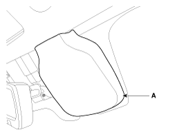
Remove the LDWS & rain sensor cover (A).
|
| 7. |
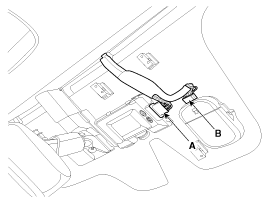
Disconnect the Lane Departure Warning System (LDWS) connector
(A) and rain sensor connector (B).
|
| 8. |
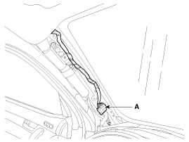
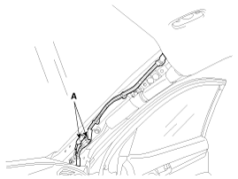
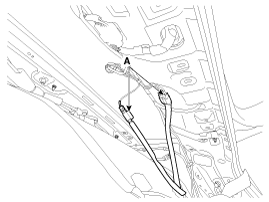
Disconnect the connector (A) and the mounting clips in the front
pillar.
[Driver's]
[Passenger's]
|
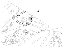
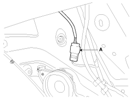
| 9. |
Disconnect the connector (A) and the mounting clips in the rear
pillar.
[LH]
[RH]
|
| 10. |
Slightly lower the rear side of the roof trim.
|
| 11. |
Disconnect the roof antenna connectors (A).
|
| 12. |
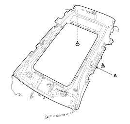
Detach the clips, then remove the roof trim assembly (A).
|
| 13. |
Remove the vanity lamp.
(Refer to "Vanity Lamp" in BE group)
|
| 14. |
Remove the hands free mic.
(Refer to "Hands Free Mic" in BE group)
|
| 15. |
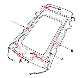
Remove roof trim wiring harness (A) from the roof trim (B).
|
| 16. |
Install in the reverse order of removal.
|
 Roof Trim Components
1. Headliner
2. Sunvisor
3. Assist handle
4. Assist handle mounting bracket
5. Room ramp
6. Sunvisor mounting cover
...
 Interior Trim Components
1. Front pillar trim
2. Center pillar lower trim
3. Center pillar upper trim
4. Front door scuff trim
5. Rear door scuff trim
6. Cowlside trim
7. Rear pillar trim
8 ...
See also:
Setup
Display Settings
Press the
key Select
[Display] through
TUNE knob or
key Select
menu through
TUNE knob
Mode Pop up
[Mode Pop up]
Changes selection mode
During On state, pr ...
Tire Removal
1.
Remove valve core and deflate the tire.
2.
Remove the side of the tire bead area from the wheel using tire
changing machine .
...
Front Fog Lamps Installation
1.
Install the front fog lamp bulb.
2.
Connect the fog lamp connector.
3.
Install the front tire wheel guard.
...
Copyright ® www.ksmanual.com 2014-2025

