 Kia Sorento: Relay Box (Engine Compartment) Inspection
Second Generation XM (2011-2024) / Kia Sorento XM 2011-2024 Service Manual / Body Electrical System / Fuses And Relays / Relay Box (Engine Compartment) Inspection
| 1. |
Disconnect the negative (-) battery terminal.
|
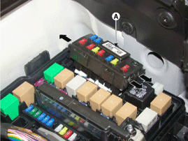
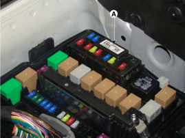
| 2. |
Pull out the relay from the engine compartment relay box.
|
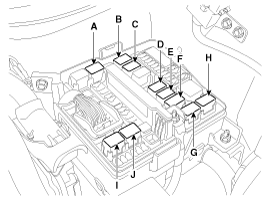
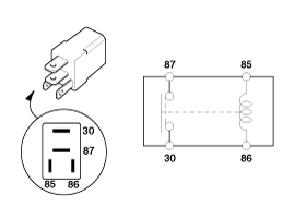
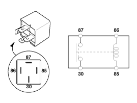
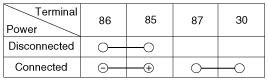
Power Relay (Type A)
Check for continuity between the terminals.
A : Start relay #1
B : Windshield deicer relay
C : Power outlet relay
D : Burglar alarm horn relay
E : Head lamp RH relay
F : IGN 1 relay
G : IGN 2 relay
H : Rear glass defogger relay
I : Horn relay
J : Blower relay
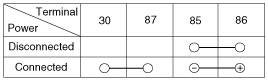
| 1. |
There should be continuity between the No.30 and No.87 terminals
when power and ground are connected to the No.85 and No.86 terminals.
|
| 2. |
There should be no continuity between the No.30 and No.87 terminals
when power is disconnected.
|
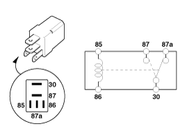
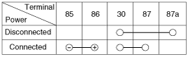
Power Relay (Type B)
Check for continuity between the terminals.
A : Wiper relay (Low)
B : Start relay #2 (W/O immo./smart key)/ ACC relay (With smart key)
| 1. |
There should be continuity between the No.30 and No.87 terminals
when power and ground are connected to the No.85 and No.86 terminals.
|
| 2. |
There should be continuity between the No.30 and No.87a terminals
when power is disconnected.
|
| 3. |
There should be no continuity between the No.30 and No.87 termianls
when power is disconnected.
|
Power Relay (Type C)
Check for continuity between the terminals.
A : Condenser pan relay #1
| 1. |
There should be continuity between the No.30 and No.87 terminals
when power and ground are connected to the No.85 and No.86 terminals.
|
| 2. |
There should be no continuity between the No.30 and No.87 terminals
when power is disconnected.
|
Fuse
| 1. |
Be sure there is no play in the fuse holders, and that the fuses
are held securely.
|
| 2. |
Are the fuse capacities for each circuit correct?
|
| 3. |
Are there any blown fuses?
If a fuse is to be replaced, be sure to use a new fuse of the
same capacity. Always determine why the fuse blew first and completely
eliminate the problem before installing a new fuse.
|
Multi Fuse
|

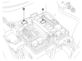
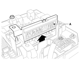
Replacement of EMS block
| 1. |
Disconnect the negative(-) battery terminal.
|
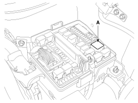
| 2. |
Push 3 hooks in the engine room relay box out to the arrow direction
and put up the EMS box assembly (A).
|
| 3. |
Disconnect the connector and remove the EMS box assembly (A).
|


See also:
Fault Diagnosis
Features a fail-safe mechanism that provides "limp-home" 4th gear hold
to enable the vehicle to be driven to the owner's home or dealer shop.
Fail-Safe: The TCM provides 4th ge ...
Fuel Line Installation
1.
Install in the reverse order of removal.
...
Installation
•
Install the component with the specified torques.
•
...
Copyright © www.ksmanual.com 2014-2024